
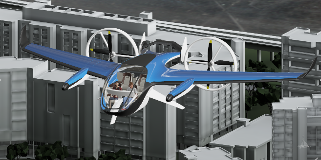
Flying cars sound like a thing of the future, but with rapid advancements in technology, they are closer to reality than ever before. Vertical Take-Off and Landing (VTOL and electric eVTOL) aircraft promise to revolutionize transportation and mobility, making our commute traffic and congestion free by entering the third dimension.
The latest trend in the VTOL industry is that of electrification and we see several startups developing eVTOL aircraft.
For the eVTOL industry, which aims to win public acceptance for very high-volume flight operations, safety is of paramount importance. The Federal Aviation Administration (FAA) and European Union Aviation Safety Agency (EASA) are working closely with Urban/Advanced Air Mobility (UAM/AAM) stakeholders to establish and improve safety standards. Until now, winged eVTOL aircraft developers such as Joby Aviation, Archer, and Beta Technologies have been progressing toward FAA certification.
Composite materials are essential to eVTOL vehicles
An eVTOL vehicle can be used as an urban taxi or as a delivery vehicle for cargo or medical supplies, regardless of the usage one rule applies to all eVTOLs: the lighter the better. The use of composite technologies in an eVTOL airframe will remain central to its success because of its lightweight, high strength-to-weight, and high stiffness-to-weight properties.
These vehicles have to be designed for composite damage tolerance under different categories of potential damages. Aircraft vulnerability can be categorized as accidental damage and crashworthiness. The below table shows different events in aircraft vulnerability:
| Accidental Damage | Crashworthiness |
| Bird strike damage | Emergency Landing |
| Barely Visible Impact Damage(BVID) | Ditching |
| Fatigue failure | Crash event |
| Lightning strike | |
| Uncontained rotor failure |
How the vehicle can safely survive such events needs to be addressed by vehicle designers and developers in the design phase, through the use of physical simulation.
Here’s the problem with Composites
Despite the advantages mentioned above, composites are susceptible to complex defects during the manufacturing process or during the service life of a component which can significantly reduce the residual strength and stiffness of a structure. Delamination is one of the most common defects in composites, which can originate both during manufacturing due to processing discrepancies or while the vehicle is in service. Delamination is the discontinuity of the interface between two or more plies. Delamination may form from matrix cracks that grow into the interlaminar layer or from low-energy impacts coming from the accidental damages mentioned above. Barely visible damages to aircraft components are hard to detect during visual inspections and this makes delamination in composites critical. Such initial delamination may propagate due to operational loads and can cause catastrophic failures under severe loading conditions. It is essential to analyze the initiation and subsequent evolution process of this kind of defect accurately when exploring the strength of composite laminates.
Register for the upcoming Tech Talk Parametric Composite Defect Template for Urban Air Mobility on November 23rd!
That being said, it is exceedingly difficult to model and simulate defects in composites. This may require multiple tools to model composite layers, and their properties and to solve further. SIMULIA has a suite of simulation tools that have been used extensively in the aerospace industry for several decades to address structural requirements, damage tolerance, and assessing aircraft vulnerability to address certification requirements.
Abaqus, a leading industry tool, has three methods to simulate delamination in composites: Virtual Crack Closure Technique (VCCT), Cohesive behavior, and eXtended Finite Element Method (XFEM). For the study shown in this blog, we used the VCCT method as it accurately predicts crack onset while being computationally cheaper.
Considering composite damage tolerance certification several challenges need to be addressed:
- Is it possible to efficiently use simulation to evaluate damage tolerance?
- How can we quickly perform multiple complex damage analysis trials?
- How can we capture and share crashworthiness assessment know-how among different stakeholders?
- Can we use FE simulation in defining guidelines for appropriate repair procedures in the structure repair manual which drive compliance with certification standards
This blog shows an example of an electric Vertical Take Off and Landing (eVTOL) cabin region and delamination modeling in it to study the effect of defects in crashworthiness analysis.
Using Engineering Templates to simplify defect modeling
We used Engineering Template, an application on the 3DEXPERIENCE platform that allows the user to efficiently reapply the operations stored in the template to other database components such as products, simulations, or parts. An Engineering Template was prepared to model delamination geometry in any part in a reusable format. This template encompasses an assembly that contains reference geometry, a so-called abstraction shape, and a finite element mesh (FEM) representation. The abstraction shape allows the user to work on a linked copy of the reference geometry, so if the reference geometry is changed, operations stored in the abstraction shape are automatically applied to the copy.
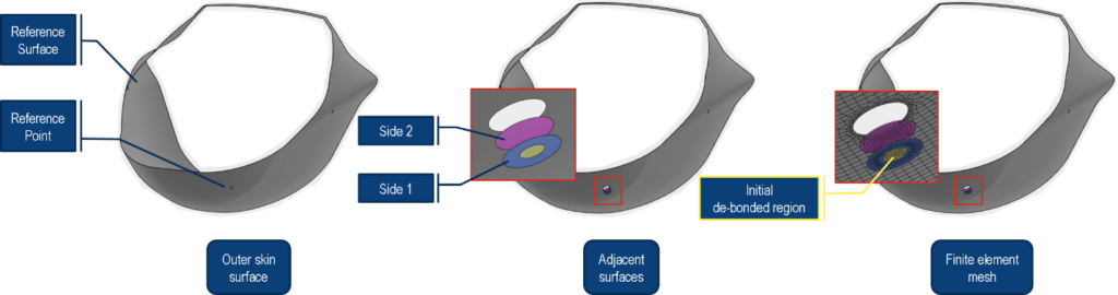
Fig. 1 shows operations stored in the template. The baseline or reference geometry is a planar rectangular surface and has a reference point positioned on it. By taking the reference point as the center, it creates a circular cut on the planar surface with a diameter value exposed to a parameter as shown in step 1 of Fig. 1. Two adjacent faces Side 1 and Side 2 are created in the abstraction shape to model the delamination. These surfaces are coincident even though their distance is exaggerated in Fig. 1 for illustration purposes. Side 1 has an inner (yellow) circle which is required for specifying the initial delamination region. Again, the diameter of this inner circle is controlled by a parameter. Finally, a quad-dominant shell mesh is created on this geometry, and section properties are assigned to the mesh shown in steps 3 and 4 respectively in Fig. 1.
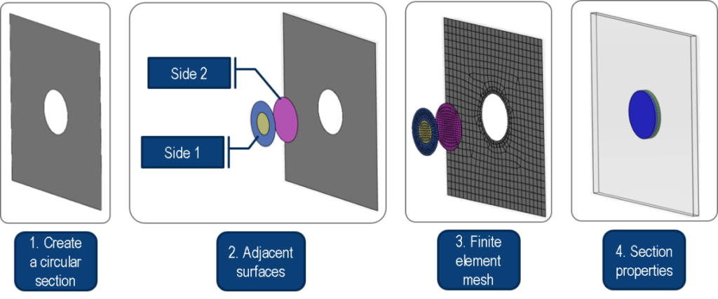
The template exposes parameters such as circular cut diameter, initial delamination size, and mesh size. While defining the template, the reference geometry from the baseline assembly was selected such that it can be replaced with another geometry from the new context at instantiation. After instantiating the engineering template, the replace mechanism reroutes all links to the replacing reference and performs all the operations on this new reference.
This engineering template can be instantiated on any pre-existing structural simulation model in the database to complement the model with a delamination defect idealized through the VCCT technique. The engineering template is mainly used to implement a delamination defect in terms of geometry and mesh, however, simulation definitions data for the VCCT contact was added through a so-called External Solve capability.
A simulation model for eVTOL crashworthiness analysis
Occupants’ protection in eVTOL vehicles can be ensured through crash prevention and crash mitigation. Crash mitigation can be achieved through multiple onboard systems. One way to reduce the acceleration experienced by the passenger is to dissipate the energy of the crash. The main parts of the aircraft that can absorb this energy are landing gears, the fuselage absorbers/subfloor structure, and the seats. Fig. 2 shows a graphical representation of a system-level approach to assist in the design of a crash-worthy eVTOL vehicle.
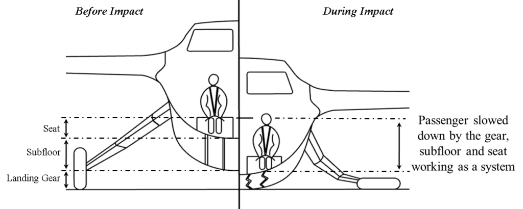
The landing gear can absorb some of the crash energy through its deformation when making ground contact. The subfloors should be capable of absorbing some of the crash impact energy and finally, the seat should be able to deform. For eVTOL vehicles, the vehicle designs will resemble smaller aircraft similar to General Aviation (GA) vehicles or utility helicopters. Certification standard for GA vehicles mentions acceleration and weight limits wherein the occupants’ acceleration in the vertical direction is given in terms of gravity. E.g. an occupant having a weight of 53.1 kg can tolerate 25G acceleration and spinal injury does not occur below this limit.
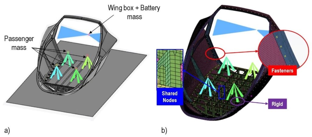
In this study, a detailed design model of an eVTOL vehicle cabin was developed based on the conceptual optimization presented previously in this blog. The model presented in Fig. 3a has a 4-passenger capacity and consists of a floor structure including lateral and longitudinal frames, a rectangular floor platform, circumferential frames, an outer skin, and other stiffened structures. To perform a finite element analysis for crash simulation, the model meshed with shell elements as shown in Fig. 3b. The wing box and battery were idealized as point masses. Different parts of the structure are connected through point fasteners, shared nodes, and rigid connections. An explicit dynamic analysis was carried out for 60 ms with gravity load and a drop velocity as per standard.
When designed properly, composite materials can work as crushable structures that absorb energy during impact to protect occupants from shock and injury during a crash. The crushing behavior in composite structures subjected to impact can be properly modeled with the CZone technique available in Abaqus. In the crash simulation presented in this paper, the CZone technique was used to model the crushing behavior of composites for different parts including the subfloor structure and the outer skin.
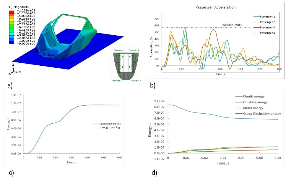
Vertical acceleration was measured at the four-passenger locations using history output. The overall displacement plot is shown in Fig. 5a. The passenger acceleration is plotted using a SAE180 filter. Since we only considered the energy absorbed in the subfloor structure while other energy absorption methods explained earlier are ignored; the acceleration is around 57G. Please note in this cabin model only the floor structure is modeled for energy absorption out of all methods represented in figure 2. The objective of this study is to understand the effect of pre-existing delamination defects on passenger acceleration therefore we consider this as our baseline result for further study. Since the CZone technique was used to model crushing behavior, energy absorbed through crushing contact is observed in graph 5b. Graph 5c shows that as the analysis progresses, the energy absorption increases and reaches a constant value at some point after the crash event. The kinetic energy in the crash simulation is absorbed through composite crushing and creep dissipation energy as observed in Fig. 5d. This simulation model was further used to implement the delamination defect through the engineering template prepared earlier.
Predicting the effect of delamination defect
In fatigue and damage tolerance (F&DT) studies, Urban/Advanced Air Mobility (UAM/AAM) vehicle manufacturers would ensure structural integrity in different scenarios. To limit structural damage and enhance flight safety during the service life of the aircraft they need to perform extensive analyses using available methods on detailed designs of different parts of the aircraft. We use the Engineering Template prepared earlier to implement a delamination defect in the detailed design crash model of the cabin region to study the effect of such a defect on passenger acceleration. The template creates the required surfaces Side 1, and Side 2, and meshes them as illustrated in Fig. 6
Once updated, the crash simulation object recognizes the modified geometry and streamlines all loading conditions with this new geometry. External Solve function allows using a script in the background that adds VCCT contact definitions between Side 1 (slave surface) and Side 2 (master surface) to the simulation model and also assigns section properties by updating the composite layup in the defect region. The inner yellow circle of Side 1 (see Fig. 6) serves as the initially delaminated region whose diameter can be controlled by the Engineering Template during instantiation. The nodes on the outer blue region in Side 1 are initially bonded slave surface nodes and the initial delamination can propagate into this region. A fracture criterion with BK law was set for the selected composite material. As the actual energy release rate in the analysis reaches the critical limit defined by the BK law, the delamination propagates into the initially bonded region. In this study, four scenarios in terms of delamination size and location listed in Table 2 are considered to analyze the effect of a delamination defect on the structural response. In this blog let’s see what happens in higher defect-size scenarios.
Table 2. Defect scenarios
| Defect part | Outer skin | Lateral frames |
| Defect Diameter | 30 mm | 30 mm |
| 39 mm | 40 mm |
A. A Defect in the outer skin of the eVTOL
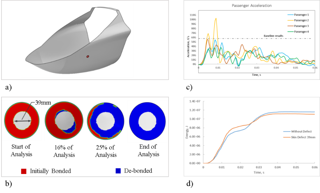
A delamination defect with a diameter of 39mm is implemented in the outer skin at the location shown in Fig. 7.a. In terms of simulation results, passenger acceleration, delamination propagation and the effect of the delamination on energy absorption are of interest. The initial delamination of 39mm propagates further as fracture criteria reach the set threshold. Plots of the bond state variable (BDSTAT in Abaqus) shown in Fig. 7.b illustrate how the delamination propagates with the analysis time. With this initial delamination size, the acceleration at passenger location 2 exceeds the peak acceleration from the baseline results significantly. The change in energy absorption during crushing is observed in Fig. 7.d. The presence of a delamination defect in the outer skin reduces the capacity of the cabin to absorb energy in comparison to the model without any defect.
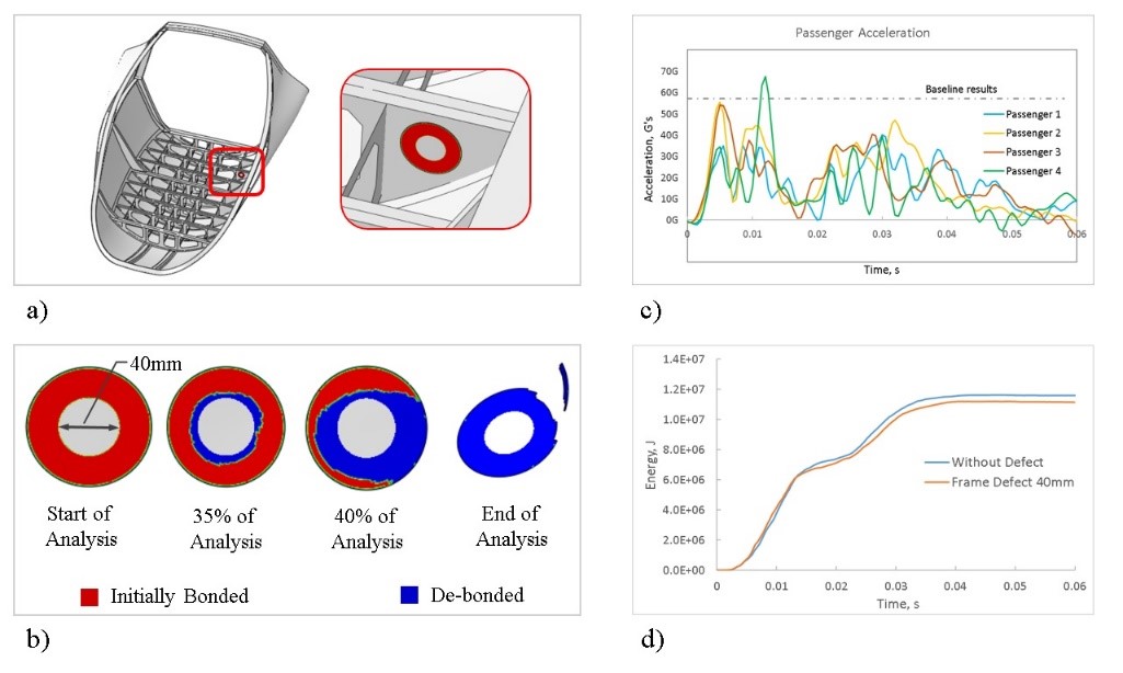
B. A Defect in the lateral frame of the eVTOL
Using the same Engineering Template, a 40mm defect is implemented in one of the lateral frames in the floor structure. This particular frame shown in Fig. 8.a is selected because it is this frame that first gets in contact with the ground in the initial stage of the crash analysis. As the defect is now located in the crushing frame structure, delamination propagates beyond the defect region, as observed in Fig. 8.b. Acceleration at passenger location 4 surpasses the baseline results (see Fig. 8.c) and reduced energy absorption through crushing is observed in Fig. 8.d when compared to the model without defect.
Let’s see the comparison between displacement and acceleration in the baseline model without a defect and with a defect in the outer skin.
Conclusion
So far we have seen how to model eVTOL crashworthiness and how to implement delamination defects to analyze its effect on overall displacement. With the template approach, we can minimize errors in complicated modeling and use the template approach to run multiple configurations. Although an eVTOL crash simulation was presented in this paper, the proposed approach to creating engineering templates for defect modeling is useful in any other type of simulation model. Such a template approach can capture corporate engineering knowledge and help to easily share modeling and simulation know-how among all users. Simulation automation allows analysts to focus more on studying the effect of defects and improving designs to ensure passenger safety. Understanding such effect of defects helps define repair manuals’ guidelines, as required for achieving type certification.
For more details, please refer to our full-length paper presented at AIAA Aviation Forum 2022 in the SIMULIA Community, here.
Don’t miss the upcoming Tech Talk, Parametric Composite Defect Template for Urban Air Mobility, on November 23rd!

Vishal Savane is a R&D roles Portfolio Engineering Manager at SIMULIA, Dassault Systèmes. He is part of SIMULIA’s strategic initiatives group and working on developing various initiatives. Vishal has more than 10 years of experience and his area of expertise is additive manufacturing process simulation, eVTOL structural design, virtual damage modelling, structural simulations, machine learning and optimization. He has published several research papers on Additive Manufacturing and on Urban Air Mobility. Vishal has completed his masters in technology and is based out of Pune, India.