Designing a Compact Ridged Waveguide Filter
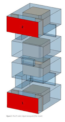
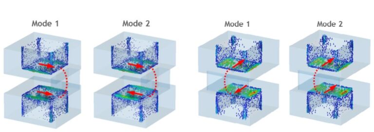
Multi-mode cavity filters offer high power handling and good performance as a compact device. Such filters are complex and sensitive to changes in the structure, meaning that their design can be time-consuming or even impossible with conventional methods. This article shows how the CST® filter synthesis tool Filter Designer 3D, part of the simulation software CST STUDIO SUITE®, can be used to design and tune a multi-mode compact ridged waveguide filter to meet stringent specifications.
The proliferation of mobile communication systems and protocols mean frequency spectrum is increasingly restricted – realizing the stringent channel specifications require high-performance band-pass filters. Satellite systems in particular are very exact in frequency, power, size and weight requirements: the filter response should produce steep cut-off to avoid channel interference and adhere to different standards,  but size and space are typically restricted. Cavity filters are typically the preferred choice due to their power handling capabilities, but they are often bulky and heavy. Multi-mode cavity filters are therefore an attractive alternative. They use a number of modes in a single cavity, which significantly reduces the overall size. They also allow cross-couplings between cavities for a better filter response, which is not always possible for single mode resonators due to physical restrictions.
There are several simulation techniques that can be used in the tuning process of coupled-resonator filters. One traditional approach is to sequentially build up the filter by adding only one resonator at a time, while the group delay of the reflected signal is used as the figure of merit for the optimization. Another approach is to apply the inverse chirp Z-transformation to the reflected signal and from the transient response identify the individual detuned resonators and couplings. It is also possible to add additional ports to the full-wave simulation model and connect lumped components in a coupled schematic for space mapping[. All of these techniques typically involve using an equivalent circuit as a surrogate model where intermediate results can quickly be obtained as a reference during the process.

