
In our unified approach, we connect a conceptual level full aircraft model to a detailed subsystem structural model maintaining load data and parameterization. We demonstrate this by performing buckling analysis of an eVTOL wing to find the best configuration subject to constraints.
With the advent of technology that enables Electric Vertical Take-Off and Landing (eVTOL) passenger flights, competition among players in this new market for mobility is fierce. In order to stay ahead in this emerging industry, multiple startups and original equipment manufacturers (OEMs) must take advantage of new tools and methods to streamline the development process when designing new air vehicle concepts from scratch.
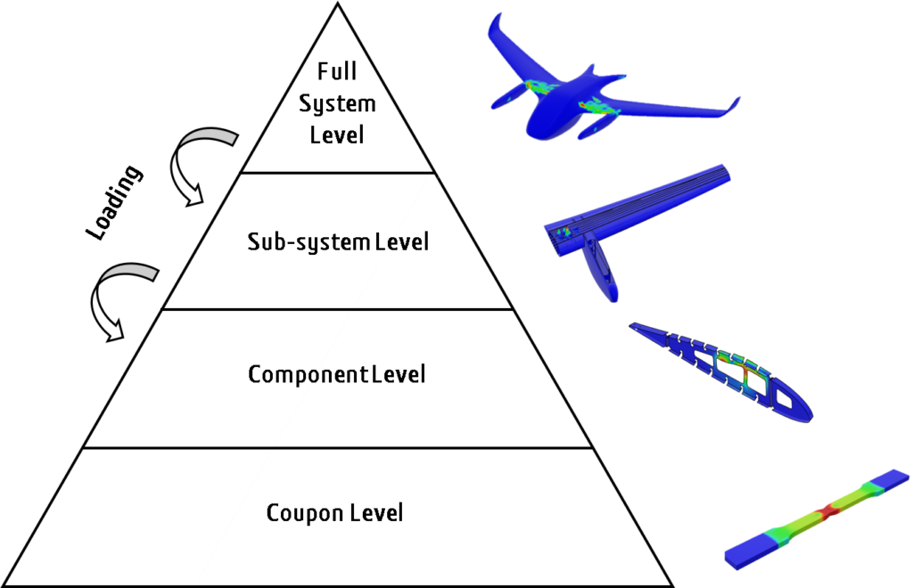
Throughout the design process of an aircraft, structural models are built at different levels of complexity, from full system down to individual component level. In early phases, coarse representations of the full vehicle structure are used for initial sizing activities while refined models of sub-systems are built in later phases for detailed sizing. Load data is typically generated at full vehicle level and must be accurately transferred and applied to detailed models of sub-systems.
Challenge with Aircraft Structural Design
It is often challenging to synchronize all models involved in the process with the latest design data since the models are typically built in a disconnected manner. This has implications for engineering as well: load information (e.g. aerodynamic pressure data) is typically generated at full vehicle level and must be accurately transferred and applied to structural models at lower levels. But a disconnected model build process makes this load transfer between the different model levels more challenging and potentially introduces inaccuracies.
The main components of vectored thrust or lift + cruise type VTOL vehicles include wings, fuselage sections, distributed electric propulsion (DEP) systems and other equipment or subsystems. The eVTOL wing can be attached to the fuselage at the top, mid or bottom, and may extend perpendicular to the horizontal plane of the fuselage or angle up or down slightly. The structural behavior of eVTOL wing structures is complex since the skin is susceptible to buckling. However, skin buckling does not lead to immediate structural failure, since loads beyond skin buckling can be sustained. Hence, accurate nonlinear post-buckling simulations are required to predict structural failure.
Check out the eSeminar, Unified Development Study from Conceptual to Detailed Structural Design for eVTOL on March 29th!
To overcome the limitations of a disconnected model build process, we propose a unified workflow that connects structural models at different system levels and enables seamless load transfer between the models while ensuring associativity with parametric design data In this study, two structural models i.e., a conceptual model at full vehicle level and a detailed wing model are embedded in same design environment on the 3DEXPERIENCE platform. The focus of this study is on simulations for the detailed wing model. In the first step, linear buckling analyses are performed on parametric geometry to find the best configuration of the wing structure subject to constraints on the skin buckling load. For final validation, a fully nonlinear analysis provides information on the post-buckling behavior up to collapse.
Conceptual Structural Optimization of the Full eVTOL Vehicle:
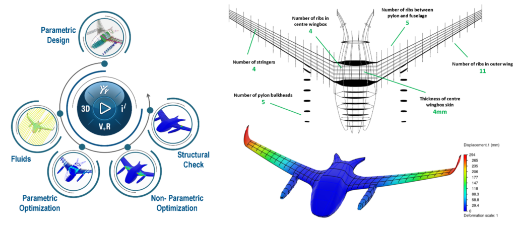
An earlier published blog explains a conceptual structural optimization based on a combination of parametric and non-parametric optimization techniques, as illustrated in the flow diagram of Fig. 2. The internal airframe structure was designed and optimized for two exemplary load cases from a typical flight envelope. The top right image in Fig. 2 shows the final vehicle configuration in terms of internal structures like ribs, number of stringers, center wing box configuration etc. The image on the bottom right in Fig. 2 shows displacement results for the Positive limit load case. We propose an approach to connect a detailed structural model of the wing sub-assembly to the conceptual full vehicle model and drive the detailed design from full vehicle loads data. This is achieved through a submodeling technique on the 3DEXPERIENCE platform.
Parametric Detailed Wing Model of an eVTOL
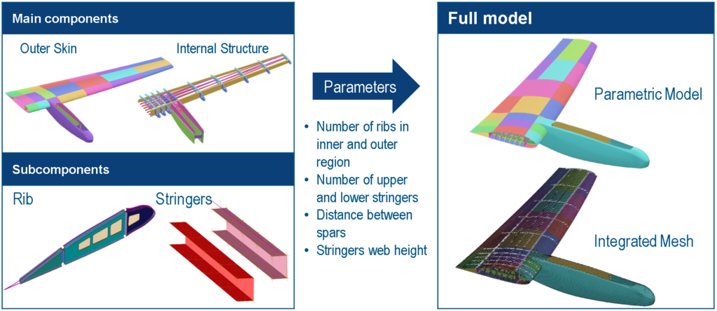
By referring to a previously used outer eVTOL surface, we built the parametric detailed geometry of wing inner structures including ribs, stringers, cutouts and spars in CATIA® SFE CONCEPT®. This tool allows creating and modifying implicitly parametric surface models fast and efficiently. The parametric geometry of the wing inner structure is projected onto the outer skin. Sub components of the inner structure (ribs, stringers, cutouts) are prepared unitarily and separately, which automatically gets instantiated into the final geometry for a given combination of parameters. A finite element (FE) mesh was also created along with the 3D geometry within the same environment. Shell elements are used for the meshing and different internal structures and they are connected using point fasteners.
The SFE CONCEPT model is used in batch mode on 3DEXPERIENCE platform to automatically generate the model corresponding to a given set of parameter values. This process also updates the FE model and all shell section definitions. The video below shows how the model is changing when parameter values for no. of ribs, no. of stringers, web height of stringers etc. are modified.
Unified Development of an eVTOL Wing Sub-system for Buckling Analysis:
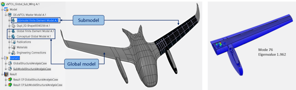
When an eVTOL vehicle is in upward flight, the wing will bend upward causing the bottom skin to be under tension and the top skin to be under compression. As the top skin of the wing is subjected to compressive stresses, it may experience buckling at a certain load level. In this study, we perform buckling analysis using the detailed wing model discussed above and carry out a parametric design exploration to minimize the weight subject to buckling constraints. On the 3DEXPERIENCE platform, within a single master Product the conceptual eVTOL model (global model) and the detailed wing model (submodel) including their respective finite element meshes are created (Fig. 4). The overall displacement degrees of freedom from the conceptual structural model are transferred to the wing model using submodel boundary conditions along the shared boundaries. All other loads including aerodynamic pressure, rotor forces and gravity are applied for the positive limit load case. We used homogeneous composite properties in this study. A linear eigenvalue buckling analysis is performed to determine the lowest skin buckling loads for the positive limit load case. Right hand side image shows the first positive eigenmode for the initial wing configuration, which has a wing weight of 153 kg (Fig. 4).
In a next step, a design of experiments (DOE) is performed using automated simulation process to explore the design space further to minimize the wing mass while ensuring that no skin buckling occurs below limit load. Using the Latin Hypercube DOE method, different parameters like no. of ribs, stringers, shell thicknesses are varied to explore the weight of the wing and the first positive eigenvalue from the buckling analysis.
The video below shows the automated DOE process. After solving around 140 iterations, analytics on the results are performed. The objective here is to minimize the wing mass while observing the first positive eigenvalue is greater than or equal to 1.0. A correlation table is plotted which shows correlation coefficients between different variables. It is observed that the wing mass is primarily affected through stringer thickness, number of ribs in the outer region and the stringer count in both the upper and lower regions. Skin thickness in the first two zones and the number of stringers in both upper and the lower region have a strong influence on the first positive eigenvalue.
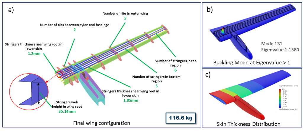
The best design variation with respective parameter values that meets skin buckling requirements at limit load is represented in Fig. 5a. The first positive eigenvalue for this configuration is observed as 1.1580 and the respective buckling mode is shown in Fig. 5b. The outer skin thickness distribution is presented in Fig. 5c. This configuration has a total weight of 116 kg, which is 24% less than baseline configuration.
Nonlinear Post-Buckling Analysis for Design Validation:
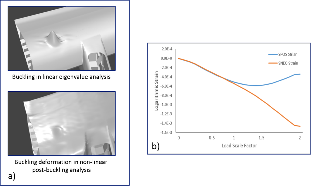
In order to investigate the post-buckling and collapse behavior of the wing structure in more detail, a fully nonlinear analysis is performed on the final wing configuration. An implicit dynamic procedure for quasi-static applications is selected. Fig. 6 shows exemplary results from the nonlinear post-buckling analysis. The images on the left show a comparison of the buckling pattern from the linear eigenvalue analysis and the one observed in the fully nonlinear analysis. The graph on the right compares local strains at the top (SPOS) and bottom (SNEG) of the upper skin in the region where skin buckling occurs enables us to more accurately determine the skin buckling load: local bending strains due to skin buckling are observed near the limit load.
Benefits from the Unified Approach on the 3DEXPERIENCE platform:
We propose a unified workflow that connects structural models built at different detail levels of an eVTOL vehicle. In this case conceptual full vehicle level and detailed sub system level wing model. The approach enables the seamless load transfer between the models while ensuring associativity with parametric design data. A structural design problem of the eVTOL wing considering buckling constraints is presented in this study. The submodeling technique is a key enabler for consistent load transfer between the models at different levels. Based on a design of experiments on the detailed wing model, a best alternative for the wing structure that meets skin buckling requirements is found. In a final step, the structural behavior of this wing configuration is validated through a fully nonlinear post-buckling analysis.

Join a community of simulation enthusiasts focused on advancing the use of SIMULIA simulation solutions in science and engineering! It’s free and easy. Start a discussion with other members of the SIMULIA Community. Talk through your simulation questions with peers, SIMULIA experts, and SIMULIA Champions. Apply to be an author to create posts, share useful tips you discovered for SIMULIA software, and establish yourself as a thought-leader. The SIMULIA Community is home to both SIMULIA product users and SIMULIA subject matter experts around the world.

Vishal Savane is a R&D roles Portfolio Engineering Manager at SIMULIA, Dassault Systèmes. He is part of SIMULIA’s strategic initiatives group and working on developing various initiatives. Vishal has more than 10 years of experience and his area of expertise is additive manufacturing process simulation, eVTOL structural design, virtual damage modelling, structural simulations, machine learning and optimization. He has published several research papers on Additive Manufacturing and on Urban Air Mobility. Vishal has completed his masters in technology and is based out of Pune, India.