
Ball-Grid-Array (BGA) Solder Joint is a common electronic packaging connection widely used in the High-Tech, Transportation & Mobility, and Aerospace & Defense industries. You can find electronic devices with BGA connections everywhere – from small gadgets like phones and watches to large vehicles and airplanes. These tiny solder balls actually play an important role in vehicle safety. According to a Reuter’s Business News, on December 22, 2015, a US automotive OEM recalled “313,000 older cars for headlight failures linked to 11 crashes” to replace the lighting control module with an increasing “risk of crash at night” due to cracked solder joints. It’s not difficult to find similar car recalls on the internet. Solder joints are one of the smallest parts that can cost automotive OEMs millions of dollars.
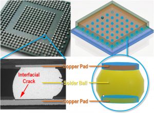
Why are BGA solder joints so vulnerable to the vehicle’s daily operation? Electronic modules with BGA solder joints are made of materials with a thermal mismatch, which can give rise to residual stresses during manufacturing and working cycles. Under thermal cyclic loading, cracks can initiate and grow near voids and other defects, as well as along the interface of solder balls and conductive pads, ultimately leading to the malfunctioning and failure of the electronic module.
Physics simulations are critical to understanding the failure mechanisms of the low-cycle fatigue of electronic packaging and improving the design and manufacture yield. Currently, the BGA design and simulation are carried out by Design Engineers and Simulation Specialists, separately, facing many challenges.
Today, most of the part and assembly designs rely on customized workflows and CAE plug-ins tailored for specific types of electronic packing, making it difficult to add/remove components and make design changes. The development and maintenance of these customized tools require some programming skills that Design Engineers usually lack. In addition, limited by the solving capabilities, the model size has to be reduced by removing some noncritical features and applying symmetry assumptions, which often are not necessarily accurate. These model abstractions can compromise the fidelity and accuracy of the physics simulation and lengthen the design- simulation cycle.
On the simulation side, Simulation Specialists have to manually partition and mesh parts, which can be very tedious and time-consuming. To keep the model size in check, the mesh used for simulation cannot be very refined, making it difficult to capture details in stress and strain distributions. As a result, the outcome of fatigue life predictions can be unsatisfactory sometimes.
Moreover, the communication between the two departments is a file-based manual process that relies on endless meetings and exchanges of emails and reports. It creates difficulties to update design changes and simulation results and poses a great challenge to data traceability, not to mention the potential risk of introducing versioning errors.
Here, we propose an end-to-end industry process for the BGA design and simulation that is fully based on 3DEXPERIENCE, leveraging the High Fidelity Simulation technology recently developed in SIMULIA. In this to-be process, 3D Modeling, Meshing, Computing, Results Analytics, and Business Collaborations are seamlessly included on a single digital platform. The PLM technologies and Knowledgeware-based Engineering Templates allow design and simulation models to be fully parameterized and automated in just a few mouse-clicks.
The High-Performance Computing capabilities of 3DEXPERIENCE allow the user to solve simulation problems up to 200 million degrees of freedom (DOFs) — much larger than what the direct sparse solver typically can handle. Thus, realistic shapes and relatively refined mesh can be used for the simulation without any manual work for model abstraction or meshing editing. As a result, the simulation tasks can be easily democratized from Simulation Specialists to Design Engineers, and the simulation results are often of High Fidelity and High Accuracy. The High-Performance Visualization and 3DDashboard capabilities allow light-weight model display and fast data sharing around the globe, with anyone on any device. In short, 3DEXPERIENCE provides Design Engineers with the out-of-the-box (OOTB) tools for seeking Simulation-driven Designs and the Single Source of Truth.

It is important to note that the fidelity and accuracy of physics simulations are critical to the prediction of the fatigue life of electronic packaging. In the To-Be Process, the High Fidelity Simulation technology supports the elasto-plasticity material models and secondary creep models that are widely accepted by the industry and academic communities. Corresponding to these different material models, either the damage-based Coffin-Mason rule or the creep-energy-based Darveaux model can be used for fatigue life predictions, depending on the user’s preference.
Please find more details in the replay of our recent e-Seminar in the SIMULIA Learning Community, and share your thoughts and suggestions with us.

Yunfei is a SIMULIA Technical Solutions Consultant.