
This is Part 3 in our Minex Faulting Series – Read Parts 1 and 2.
Geologists often face challenges when modelling faulted deposits, as workflows in many software packages are often manual, time consuming and costly. GEOVIA Minex aims to address this challenge with an expansive tool set of functions dedicated to making fault modeling quick and easy.
Please note you will need Minex 6.5.1 to follow the below steps.
There are 2 main methods for modeling a fault, 2D and 3D faulting. Typically, 2D faulting is applied when, little or no information is known about the fault and the fault is assumed to be dipping vertically. 2D faulting is also preferred when modeling needs to be completed quickly. In contrast 3D faulting is favoured when detailed information is known about the fault, such as dip and throw.
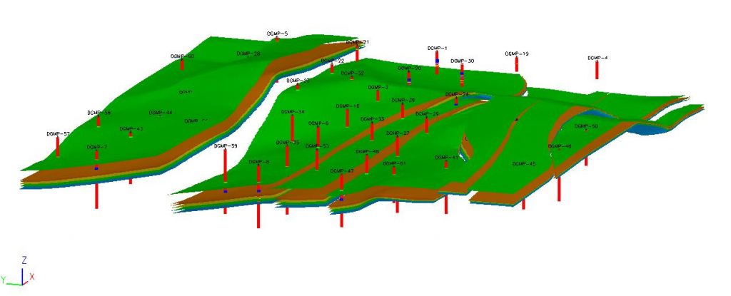
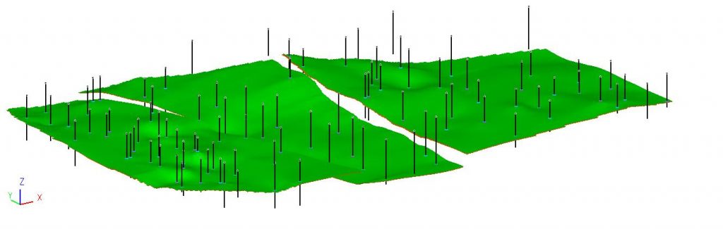
In this blog post we will now look in more detail at 3D faulting in GEOVIA Minex 6.5.1 software. An example of a 3D fault model is shown below:
Following on from Step 2 Fault Definition, outlined in our previous post, we will now look at the remaining steps of the 3D Fault modeling process.
Unfault Boreholes or Geometry
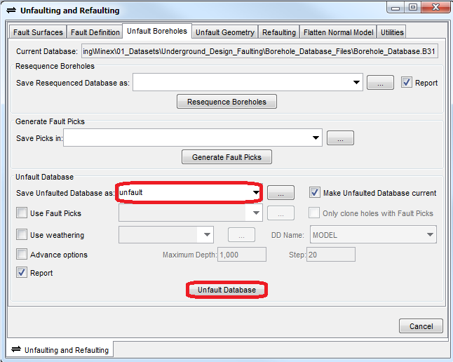
- Now that the faults are defined and the fault blocks generated, you can proceed to unfaulting. In Minex, this can be either completed on the boreholes or the geometry. In the example below we will unfault the boreholes. Go to Seam Model > Unfault/Refault and select the Unfault Boreholes tab.
- Enter an Unfault Database name and click Unfault Database, in the form below:
With the boreholes in the unfaulted position, they should be relatively flat, as this should be the geology before faulting occurred. If the seams are not smooth and near horizontal then your fault settings are likely incorrect and the above processes will need to be repeated, with the likely error associated with dip/throw values.
For example: Unfaulted Geology
Seam Modelling
Now, you can complete seam modelling processes such as:
- Father / Son (if applicable)
- Seam Splitting (if applicable)
- Set Missing Seams
Create Grids and save them into a new grid folder., for example UNFAULT.grd
- Multi-Seam Multi-Variable Gridding – SF + ST
- Seam Model Operations – Arithmetic – SR + IB
- Seam Model Operations – Model Build or Strata Build
- Seam Grid Statistics (optional validation step) – ST + IB
Refault Grids
After generating unfaulted grids either from unfaulted boreholes or geometry, the next step is to complete refaulting.
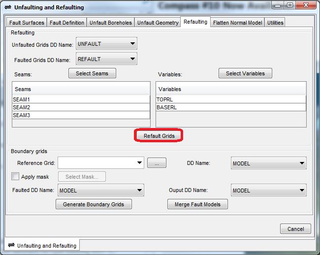
- To do this go to Seam Model > Unfault/Refault and select the Refaulting tab.
- Select input and output grid folders. E.g. UNFAULT.grd and REFAULT.grd
- Select Seams, E.g SEAM1
- Select Variables. For 3D faulting it is recommend to select BASERL and TOPRL
- Then click Refault Grids to generate the 3D faulted grid model
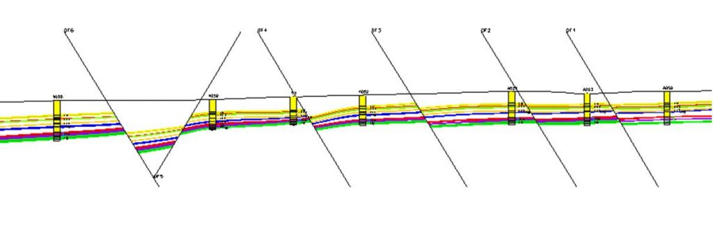
For example: Refaulted Grids:
2. Re-Compute Seam Thickness
Following creating refaulted seam floor (SF) and seam roof (SR) grids, seam thickness (ST) will need to be re-generated using the Arithmetic function: Seam Model > Seam Model Operations > Arithmetic – ST
Lastly, the model should be checked for errors visually and using the appropriate functions, such as Seam Grid Statistics. Following these standard validation checks, the fault model should be complete and ready for resource reporting.
You may also check out the below blog posts:

Ross is a qualified Resource Geologist with 9 years' industry experience in database management, geological modeling, grade control, geostatistics, resources estimations and process mapping. Since joining GEOVIA, Ross has worked with and assisted mining clients across Europe, Middle East and Africa. His commodity experience includes gold, copper, lead, zinc, iron, coal, bitumen and various industrial minerals. He regularly delivers support, training and consultancy services in GEOVIA Surpac, GEOVIA Minex, GEOVIA MineSched and various roles on the 3DEXPERIENCE Platform. Ross is based in Coventry, UK.