
In design and engineering, assumptions are often made as a simplifying mechanism, and sometimes because that simplification is sufficient. But often times it is because one doesn’t have the adequate time nor tools to account for nonlinear effects.
For many components, manufacturing processes have significant impact on product performance, but are often some of the most-commonly overlooked effects. What manufacturing effects should be considered, and which ones can be ignored? The answers to these are not always well understood. Often times, standard practice in engineering is to have designers build a design, pass that over to analysts, and then have analysts build and analyze the design. Frequently this approach is rather cumbersome and takes, as a result, longer than ideal. Because of not ideal connections and time to go from CAD to CAE, it is not uncommon to spend more time on the transfer of data and the initial analysis run than it is to actually build, analyze and understand the model.
3DEXPERIENCE Platform – Bringing Together the Design and Solid Mechanics Tools:
The 3DEXPERIENCE Platform by DASSAULT SYSTÈMES combines the world-class design features of CATIA with the linear and nonlinear solid mechanics tool sets from SIMULIA. Such a powerful capability allows for a more seamless connection between CAD and CAE than is typical in the industry. It also allows for guided processes and standardized templates, which can result in a quicker first answer. So instead of initial simplified calculations and assumptions being done by expert structural analysis engineers, these first pass answers may be embedded within the CAD and early engineering tool sets to arrive at both a first model and a first initial guess as to the structural key performance indicators. This allows for first pass linear structural answers to be executed and analyzed within the CAD before being passed along to analysts.
The structural analysis engineer can then “sharpen the blade” by further refining the model and adding appropriate effects to the “first-pass” model delivered to them. Some of these manufacturing considerations may simply be “expanded” linear assumptions, but one can include contact, material nonlinearity, and even stress-stiffening effects where appropriate. As we will see, this refinement can be crucial and can readily reveal failures that may otherwise be overlooked. Some “classic” examples of nonlinearity are material nonlinearities – plasticity in steel, nonlinear behavior of rubbers, cracking and failure in a variety of materials and components. While these are often well-understood, two other forms of nonlinearity are more frequently overlooked–the effect of contact, and the impact of “nonlinear geometry.” All three of these forms of nonlinearity can be a result of the manufacturing process, and all are readily modeled, analyzed, and post-processed on the 3DEXPERIENCE Platform.
We have evaluated two examples that demonstrate these manufacturing effects, and in particular focus on how each of these can play a part in considering the impact of manufacturing effects on systems.
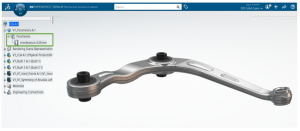
- Press Fit Connection in a Lower Control Arm:
Contact is generally well-understood by engineers – two or more components “clash” into each other, and forces are transferred between them, which give rise to stresses and strains. An example of contact that is often not considered, but can be quite critical in its implications, is that of a “press fit.” In a press fit, one component of a slightly larger outer section is “forced” into another of a smaller section, thus the name. The press fit has to balance competing requirements: too little of interference between the parts may result in a fit that can too easily pull out and compromise the integrity of the system through part separation. However, too much interference will result in high stresses and strains resulting in failure within one or both of the parts.
The simulation module within the 3DEXPERIENCE Platform readily allows the ability to not only capture such a press fit (instead of the simplified approach), but also can account for variation in the interference in order to study the resultant stresses due to the press fit itself and when those press fit stresses are included within “standard” loading. Failing to account for press fit effects can have catastrophic consequences.
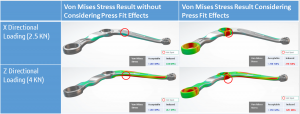
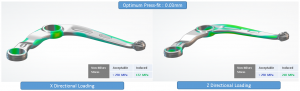
As shown in the above example, a lower control arm (which is a common example of press fit) could fail unexpectedly if the effects of the press fit are not considered during simulation. The results on the left are misguiding and could cause warranty issues for manufacturers. These kinds of unexpected failures and recalls could also affect the reputation of OEMs.
Often, in the industry, press fit effects are considered during the detailed analysis of component. Excessive press fit detected and corrected in early design stage would save overall project time and cost.
Below, we have summarized the 3DEXPERIENCE workflow to achieve this:
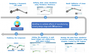
- Parametric CAD Modeling:
Parameter-based design on 3DEXPERIENCE platform leverages possibility of testing a design for its different configurations. Interference between lower control arm and bushing can be defined and varied through a design parameter as shown in the below image.
- Integrated Modeling and Simulation:
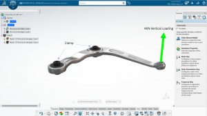
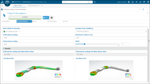
Unified platform for CAD modeling and simulation makes it easy for designer to analyze the designed component before passing it to the simulation engineer. Simulation Assistance in 3DEXPERIENCE platform can guide even a non-expert analyst to perform basic linear and non-linear simulations before passing the model to an expert analyst. In this case, two separate simulation cases for vertical load of 4KN and lateral (X directional) load of 2.5KN are defined. To ignore non-linear effects at design engineer level, bushings are tied to the lower control arm and the inner cylinder of bush is clamped.
- Reuse of Linear Simulation to Perform Advanced Non-linear Simulation:
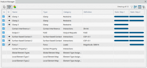
For a detailed and accurate study, design engineer can change connection parameters between bushing and lower control arm to include effects of press fit in the simulation. Associativity between CAD and FEM makes it easy to define a new simulation feature or modify an existing feature within the linear simulation. Feature manager gives a consolidated view of simulation features that are defined and makes it very easy to modify in minimum number of mouse-clicks.
- Automation and Collaboration:
An expert analyst can define simulation templates for certain well-defined workflows and make it readily available for design engineers to perform detailed analysis while considering the manufacturing effects. Web-based widgets to perform these predefined simulations drive effective collaboration between the designer and simulation engineer, who can co-review and finalize the design.
Thus, comprehensive tools on 3DEXPERIENCE platform makes it possible to optimize the press fit interference at the early design stage and avoid unwanted failures and recalls.
- Bolt Modeling in a Clevis Joint:
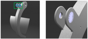
The second example of manufacturing effects is that of a clevis joint. A clevis joint is simply a coupling consisting of u-shaped linkage (sometimes called a “fork end”) through which a pin or bolt passes. This pin typically attaches to a linkage or rod, allowing the linkage to rotate about the pin while “fixing” it to the fork end in all other directions.
Clevis joints are used across a myriad of products, and are quite common in automotive and heavy equipment suspensions, in industrial machinery applications, in aerospace linkages, and in a variety of other use cases. They can be very small with a simple tiny “pin” as the joint for inexpensive home goods, but for industrial equipment and large machinery can often be so massive as to outweigh a person and require very large bolts as the “pin.a” In larger machine applications, it often is not sufficient to simply “connect” the fork end to the rod, as the bolt itself must be tightly torqued, which can add manufacturing stresses to the part before any “operating loads” are even considered. These bolted loads tend to “bend” the fork end and can result in significant pre-stresses. If these manufacturing stresses are ignored, incorrect factors of safety for operating loads can result, resulting in non-conservative peak loading stresses and over-prediction of fatigue lives.
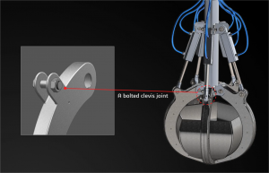
In this jaw gripper, a bolted clevis joint is used to connect the link to the jaw component. For such an assembly as this, large bolts (with associated high bolt pretensions) need to be used to avoid disconnection. The bolt loads will “pull” the clevis joint forks together and result in assembly stresses. Heavy-duty equipment as this is often over-engineered—it’s better to have some extra mass than risk down-time for such expensive equipment. But even with high factors of safety, it is important to consider how these manufacturing effects combine with operational loads.
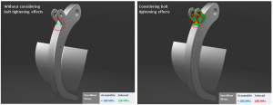
For the simulation results shown in figure 9, the operational loads by themselves result in quite modest stresses in the forks and are nearly 20% below the target stresses. However, accounting for the manufacturing-induced stresses on top of the operational stresses, actual results are 30% higher than target. Such stresses, while well below yield, may nonetheless result in eventual component fatigue, resulting in field failures and operational downtime. Hence, selecting an optimum bolt tightening force is very important to avoid these issues. 3DEXPERINCE platform provides a design friendly tool to perform these kind of simulations as summarized in the following workflow:
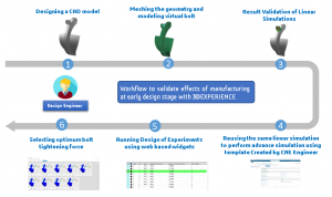
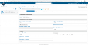
- Modeling a virtual bolt:
Defining a bolt CAD geometry to study the effect of tightening could include unnecessary complexity (like non-linearity due to contacts) for a design engineer. Hence, virtual bolt definition tool in 3DEXPERINCE provides a simplified approach to define a bolt representation as an FE entity and allow preload to study the tightening effects. The designer can simply select edges of a part or use bolt detection to define virtual bolt at clevis joint location.
- Defining a linear simulation:
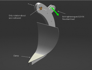
Similar to the press fit example, simulation assistance can guide the design engineer to setup the simulation. Selecting the CAD features like face, edge or vertex, the design engineer can easily define load and boundary conditions. In this case, the jaw is clamped at bottom face and 10KN of load is applied at clevis joint.
- Custom template for DOE and Optimization:
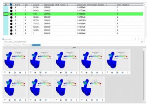
Expert analyst can define a web-based simulation template for design engineer to study effect of different values of bolt tightening force on clevis joint. Design of experiments can be formed at the early design stage itself without involving expert analyst in loop. In this case, the effect of bolt preload varying from 1KN to 5KN with difference of 500N is studied using the process composer DOE template.
- Web-based results validation in Results Analytics:
Once the process is complete, design engineer can collaborate with expert analyst to visualize results on the web-based widget referred to as Results Analytics. Just by modifying input parameters like load and bolt tightening force, the designer can reuse the template for different models that have a similar application. As shown in the images below, the design engineer can conclude that bolt force above 2KN could exceed the stress beyond acceptable limit (150 MPa).
Thus, an expert CAE engineer can concentrate on more advanced simulations and design engineer takes care of manufacturing effects at early design stage and saves overall process time and cost.
Conclusion:
If manufacturing effects are considered early during the design stage, one can more accurately understand true “factors of safety” in design. Designer friendly tools on the 3DEXPERIENCE platform can help to predict product performance more consistently and as a result can reduce warranty costs, recall costs, and operational costs for customers.
For more information about MODSIM, visit the website.
SIMULIA offers an advanced simulation product portfolio, including Abaqus, Isight, fe-safe, Tosca, Simpoe-Mold, SIMPACK, CST Studio Suite, XFlow, PowerFLOW and more. The SIMULIA Community is the place to find the latest resources for SIMULIA software and to collaborate with other users. The key that unlocks the door of innovative thinking and knowledge building, the SIMULIA Community provides you with the tools you need to expand your knowledge, whenever and wherever.

Katie is the Editor of the SIMULIA blog, an expert in engineering and scientific communication, and a strategic digital marketer. Katie has a BA in English and Writing from the University of Rhode Island and a MS in Technical Communication from Northeastern University. She is also a proud SIMULIA advocate, passionate about democratizing simulation for all audiences. Katie is a native Rhode Islander who lives just outside of her favorite city, Providence. She is a true New Englander and loves sharing all the cool things NE has to offer. She enjoys a variety of hobbies including history, astronomy, science/technology, science fiction, true crime, fashion and anything associated with nature and the outdoors. She is also mom to a 6-year old budding engineer and two crazy rescue pups.