
Want to learn how to simulate X-ray tubes in SIMULIA Opera? Don’t miss the upcoming webinar!
Part 1: Operation principles of x-ray tubes
In this two-part article, we will look at the utility of the SIMULIA Opera simulation environment for the design and analysis of X‑ray tubes. In this first part, we will concentrate on a review of the processes that underlie the operation of X-ray tubes, and the requirements that they place on tools used in their design. In part two, we will focus on the ability of Opera to meet these requirements with specific examples.
X-ray generation
Several phenomena generate X-rays, including:
- Acceleration of charged particles in a magnetic or electric field (synchrotron, or Lamour radiation)
- Acceleration of energetic electrons incident upon a material of high atomic number (bremsstrahlung – braking-radiation)
- Transition of atomic electrons from a high to low energy level
- Scattering between low energy photons and ultra-relativistic electrons (inverse Compton scattering)
These processes are responsible for X-ray generation from both natural and manufactured sources. For example, inverse Compton scattering of beta radiation produces X-rays from some radioactive materials. X-rays from a number of astronomical sources, like the Crab nebula, result from synchrotron radiation – which is also the mechanism used by many manufactured X-ray light sources.
Today we will concentrate on what we usually think of as an ‘X-ray tube’ – in which the main mechanism of X-ray production is bremsstrahlung.
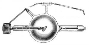
Let’s briefly consider the genesis and early development of X-ray tubes. The first purpose-designed source was the so-called Crookes tube, shown in Fig. 1(a), developed from the tubes of the same name that were used to generate and accelerate ‘cathode rays’ – later identified as electrons. In 1895 Wilhelm Röntgen first noticed that the original tubes produced emissions – X-rays – that could cause fluorescence outside the tube. These tubes used a cold cathode and contained residual gas at low pressure (<~1mTorr). A high voltage between anode and cathode generated a plasma from which the ions were accelerated to the cathode, producing secondary electrons; these electrons were accelerated towards the anode – generating more ionization en route – where they produced bremsstrahlung radiation.
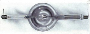
These tubes were not particularly reliable and, over time, the residual pressure reduced as the gas was absorbed by the walls of the tube; it then needed to be replenished by heating a side-tube containing a material that had previously adsorbed gas. The Coolidge tube, shown in Fig. 1(b), invented by the eponymous Dr Coolidge in 1913, improves on the performance of the Crookes tube. It uses a hot cathode thermionic emitter – often a wound cathode filament – and operates at a higher vacuum. Electrons are accelerated towards the anode where the X-rays are generated.
In this blog, we will concentrate on the Coolidge tube, which in principle is quite simple. Despite its age, modern tubes are still based on this same general concept of an electron emitter: accelerating/focusing electrode and high atomic number target – although we might now consider cold-cathode, field-effect emitters as well as hot thermionic emitters as sources of electrons.
X-ray tube characteristics
In the X-ray tube we have a beam of energetic electrons incident upon a target made from a material of high atomic number. Deflection caused by the nuclear charge of this material produces bremsstrahlung radiation and the different degrees of deflection give the radiation its wide, continuous energy (and wavelength) spectrum, with the maximum at the energy of the incident particle – as indicated in Fig. 2.
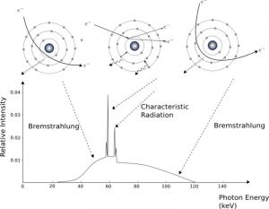
While bremsstrahlung is responsible for most of the X-ray generation, the spectrum also includes discrete energy peaks which are produced when an electron is ejected from an inner shell by a passing particle and an outer-shell electron falls to replace it, releasing a photon at the energy of the difference between the levels. Since the difference is characteristic of an atomic species, this is termed characteristic radiation.
We note here that, in principle, the intensity of the bremsstrahlung radiation would increase linearly as the energy reduces. However, in practice, the X-rays are produced at some depth in the material and also need to pass through the wall or window of the tube. Hence some absorption occurs, with the lower energy emissions being absorbed to a greater extent than those at high energies. This is known as inherent filtering;. External filtering may also be applied to tailor the spectrum, such as in diagnostic X-rays. In this case removing the lower energy components is beneficial since this region would be absorbed by the patient’s body, thus increasing the dose without giving diagnostic (transmission) data.
When the electron beam hits the target, the spatial distribution of the X-rays depends on the beam energy. At low energy, X-rays are emitted almost isotropically and most tubes have a window to allow X-rays to be extracted perpendicularly to the electron beam direction. The target is angled so that the beam incidence is a few degrees off normal, which has two effects. Firstly, as radiation is produced at a small distance below the surface, the material of the target and anode structure absorbs some of the emission – angling the target reduces the attenuation of those X-rays emitted perpendicularly to the beam direction. However, varying attenuation close to the target surface grazing angles gives a taper to the X-ray beam density on one side of the beam. This can be corrected by external filters, or can be used to minimize dose and give uniform contrast in imaging applications where the object tapers in optical thickness (this is known as heel filtering). Secondly, the apparent size of the beam incidence region (in the beam direction) is reduced by a factor of the cosine of the target angle. This smaller effective source region gives better resolution in imaging applications.
Don’t miss the upcoming webinar to learn how to simulate X-ray tubes in Opera!
As the beam energy increases, the X-ray emission becomes more directed along the beam direction. The need to reduce target and anode structure absorption means that in some tubes, the target is a thin foil, allowing X-rays to be radiated along the beam.
Only a small proportion of the kinetic energy of the electrons is converted to X-rays typically around 1% – meaning that significant amounts of heat would need to be dissipated if generating high power/long pulse X-rays. This led to designs for rotating anode tubes as early as the 1890s, which spread the heat load over an extended region, although the first practicable tube was made by Coolidge in 1915. We will come back to the issue of power dissipation later when looking at applications of X-rays, and the consequent implications for source design and analysis.
That concludes our brief review of X-ray tube operation. In Part 2 of this article, we will examine how Opera addresses the task of simulating the main processes involved in these devices, and how this enables their efficient design and analysis.

SIMULIA offers an advanced simulation product portfolio, including Abaqus, Isight, fe-safe, Tosca, Simpoe-Mold, SIMPACK, CST Studio Suite, XFlow, PowerFLOW, and more. The SIMULIA Community is the place to find the latest resources for SIMULIA software and to collaborate with other users. The key that unlocks the door of innovative thinking and knowledge building, the SIMULIA Community provides you with the tools you need to expand your knowledge, whenever and wherever.

Mike Hook is a SIMULIA Electromagnetics Industry Process Consultant.