This article was originally published in the June 2018 issue of SIMULIA Community News magazine and is the second part of a two-part article about simulating space communications with SIMULIA‘s CST Studio Suite. Read the first part, here.
PRODUCTION AND PERFORMANCE ADVANTAGES
So what advantages do 3D printed waveguides have over conventionally designed and manufactured waveguide filters? Booth sees quite a few.
“With conventionally designed waveguide filters the design software can be quick and accurate using variations of mode matching techniques,” he says. “But initially this meant waveguide filters with sharp corners everywhere that required electro-discharge machining of the parts. The parts are also usually made in two pieces, either two mirror image halves or a body and a lid, that all require assembly, usually with fasteners. Things progressed with the software to allow machining radii to be included, which certainly helped the manufacturing time—but this slowed down the design time.”

In contrast, 3D printing of waveguide components allows for optimum “organic” shaping without sharp corners, enabling better wide performance or lower insertion loss—or a tradeoff between the two. “There are also savings in mass that can be made if a monolithic part can be produced, and we have typically found the mass to be reduced more than 40% compared to conventionally machined parts,” says Booth. “If more functions can be consolidated into a single part then the mass savings can increase as there is no need for connections between what would be individual components. There is also the added benefit of reduced assembly time; two halves no longer require bolting together and potentially separate components do not need assembly. This can have quite an impact on overall cost.”
The potential freedom of design offered by additive manufacturing software must nevertheless be expressed within strict RF allowances, which is why the Airbus team turned to SIMULIA’s CST software for electromagnetic simulation. The CST STUDIO SUITE comprises CST’s tools for the design and optimization of devices operating in a wide range of frequencies, static to optical. Analyses may include thermal and mechanical effects, as well as circuit simulation.
DESIGNING THE SPACE INSIDE A COMPONENT FIRST WITH CST STUDIO SUITE
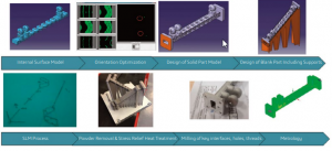
Booth describes how the team employed CST STUDIO SUITE for the ESA filter design: Starting with proprietary software, they first looked at the RF requirements to determine the filter order and whether there might be any particular challenges in achieving their aims. “We then use the CST tools to obtain the best starting geometry for the resonator using the Eigen mode solver,” he says. “Next we connect two resonators via a coupling aperture and create a graph of coupling versus aperture width—again using the Eigen mode solver. From this we can determine the size of each aperture required in the filter along with individual resonator sizes. We then create the filter in CST STUDIO SUITE and use the frequency domain solver to analyze and optimize the design. At any of these stages we may take a little step back or adjust a few parameters to improve the performance.”
The particular beauty of the CST tool is that the internal geometry of a filter—the empty space inside the component that will produce the desired RF frequency configuration—can be considered the starting point of the design process. “At the very beginning of this project with ESA we looked at specific geometries,” remembers Booth. “But now, for anything we design for satellites with CST software we only need the RF requirements to start.” With the completed design in hand, the final geometry is exported in .stp format and sent to the manufacturer, in this case Airbus Innovation Works. (The group also uses 3D Systems in Leuven and has recently added its own metal printer in Stevenage, U.K.). Finished filters undergo vibration testing to simulate space launch, as well as tests over temperature extremes in a vacuum to simulate the operating environment.

BENEFITS EXTEND DOWNSTREAM
The benefits of using 3D printing to produce the filters have proven significant, Booth notes. “It is quite easy to reduce the mass of such a component by 40–50% with 3D printing, compared to conventional machining,” he says. “On a very recent project we achieve greater than 60% mass reduction. In terms of turnaround, from the start of the design process to shipping the finished part, we can see a 10% reduction. However, for high-throughput satellites requiring a large quantity of the same design we expect this to improve significantly. Most of the cost and schedule savings are from reduced assembly processes.”
Airbus Defence and Space’s work for ESA has definitely been a team effort. “For the filters we’ve produced so far we have really needed the buy-in of all parties, but they are quite lowstressed items so the mechanical design has not been too demanding,” Booth says. “This is the same with the thermal aspects.” However, for larger, longer antenna feeds he sees the need for a much more multidisciplinary approach to allow the entire feed to be optimized as one. “Ideally, if we can use tools that are compatible with each other, maybe even integrated in a common platform, then the design process can be much more efficient,” he says.
The ultimate proof of the success of the filter project is already circulating earth, Booth notes: “I’m pleased to say that we have a filter in space at the moment with another pair to be launched hopefully at the end of this year or early next year.” The message is coming through, loud and clear.
For More Information: www.airbus.com/space
