
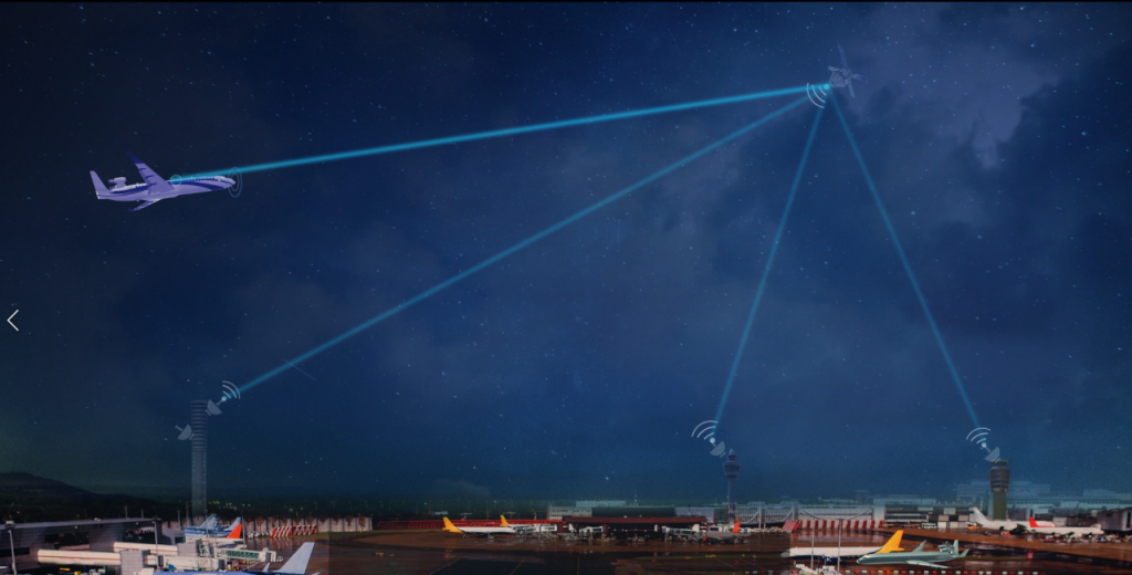
Passenger aircraft communicate with satellites to facilitate in-flight entertainment. Bringing high speed Internet into the cabin enables everything from email and social media to online shopping. A recent survey by Honeywell Aerospace concluded that two-thirds of airline passengers are choosing flights that have Wi-Fi on board. The global in-flight entertainment and connectivity market size was valued at approximately $5.9 billion in 2019.
The system on the aircraft that makes all this possible is called the Satellite Communication (SATCOM) system and it consists mainly of two separate antenna modules, one for transmitting and one for receiving. They operate in the 14 to 14.5 Gigahertz frequency band and thus need to be extremely small, as small as a peanut.
But how can such a small antenna transmit data to a satellite 36,000 kilometers away in outer space?
Well, the SATCOM antenna is not just one individual antenna, but instead is a cluster of identical pea-sized antennas all operating together at the same frequency, and they are more commonly known as Antenna Arrays. Most traditional small antennas radiate a limited amount of power, and the radiation is far from focused. This limits the coverage distance of antenna radiation.
The SATCOM transmitting antenna produces a narrow focused beam, almost as if it’s aiming for the satellite and emits all the radiation only in a specific direction. Moreover, if the link is momentarily lost, these arrays, with the help of control systems, can automatically scan for the satellite by maneuvering the beam in all directions, and once found, they can lock the radiated beam onto the targeted satellite.
For an antenna to be able to perform such intelligent tasks, it is important that they are carefully designed and validated. Using SIMULIA’s electromagnetics tools, we designed and simulated a SATCOM antenna array operating at 14 GHz.
To design the array, we performed the following steps:
- Antenna Unit Cell Modeling
- Unit Cell Optimization
- Antenna Array Modeling
- Radome Design
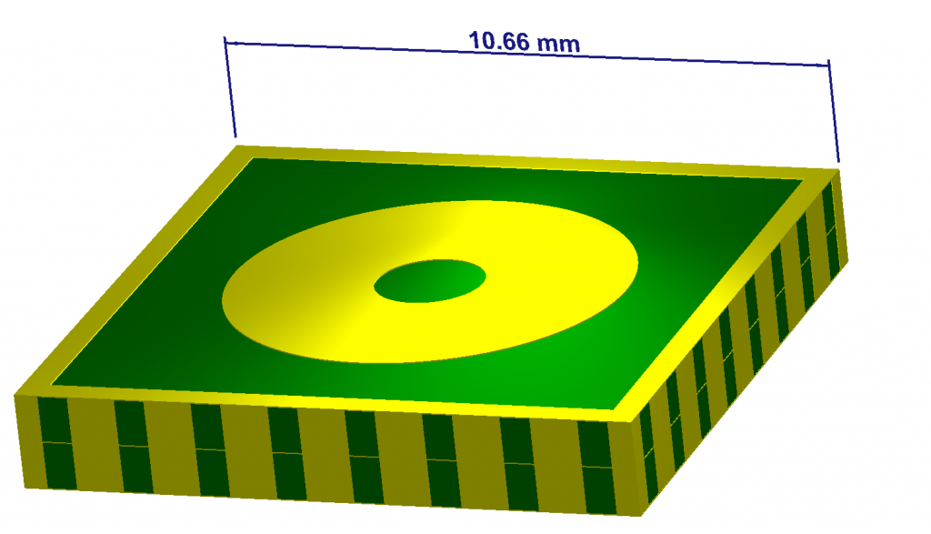
Antenna Unit Cell Modeling
The first step was to create the individual antenna element, also known as the unit cell of an array (Figure 1). SIMULIA’s modeling tools allowed us to design a parametric model of the unit element and assign appropriate material properties from an extensive material library. S11 parameters showed that the unit cell worked perfectly in the desired frequency of operation.
Optimization of Unit Cell
Now that we have the basic building blocks of our array, we should be able to put these elements together to form an array. But there’s one problem. When multiple antennas are placed close to each other, they degrade the neighboring antenna’s performance to some extent. To correct this, an optimization of the antenna’s dimensions was required.
Optimizing an entire array consisting of hundreds of elements at frequencies as high as 14 GHz is computationally very expensive. To avoid this, a special feature called “Floquet Port Boundary Conditions” allows a single unit cell to mimic the performance of an infinitely large array. The advantage of this feature is that it allows us to study the performance of the antenna array before actually designing it. So, simulations are performed on a single unit cell, not the entire array, thus saving computational time and resources.
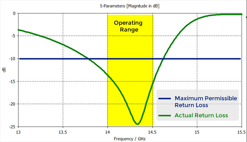
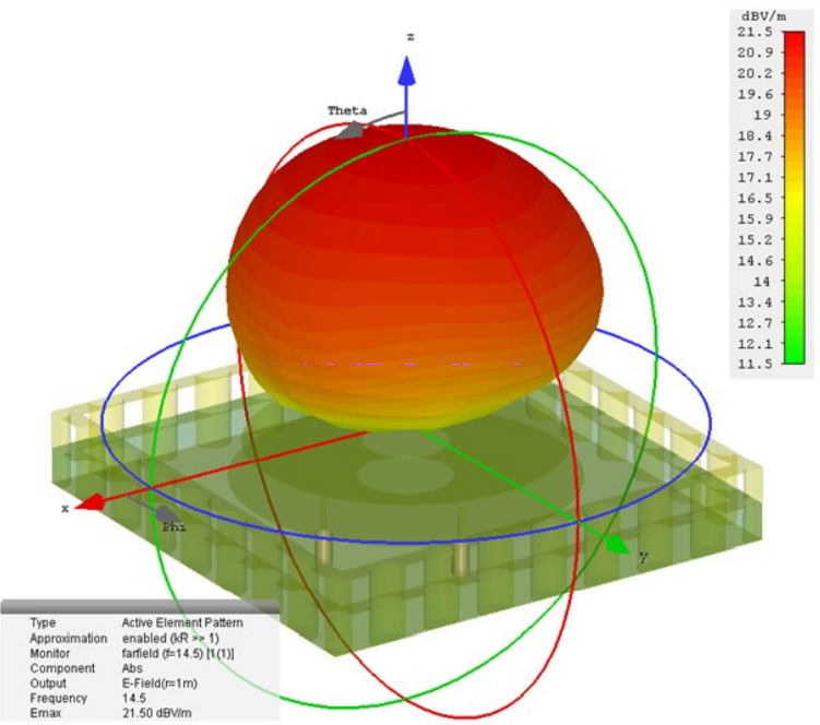
Optimization was performed simultaneously at multiple scan angles of the radiated beam as well as multiple operating frequencies in the 14 GHz to 14.5 GHz range. The goal of the optimization was to produce a unit cell design that would produce an Active Element Impedance (AEI) of not more than -10 dB when used to build an array (Figure 2).
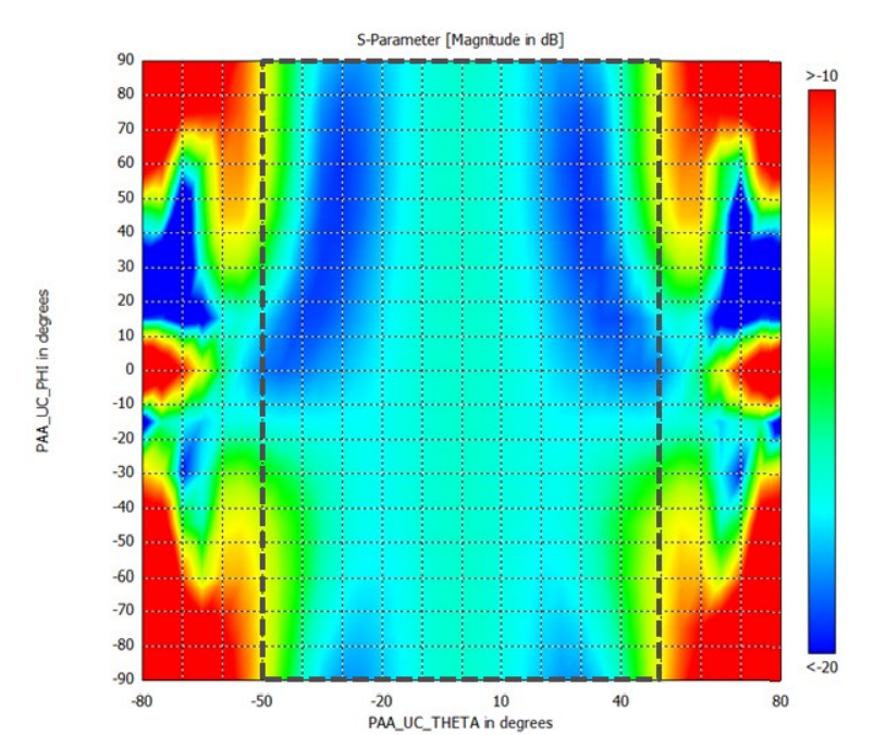
As shown in Fig. 3, the Active Element is less than -10 dB for scan angles of -50º ≤ θ ≤ 50º and -90º ≤ φ ≤ 90º (demarcated by the dashed rectangle), where the boresight axis is perpendicular to the plane of the antenna.
Antenna Array Modeling
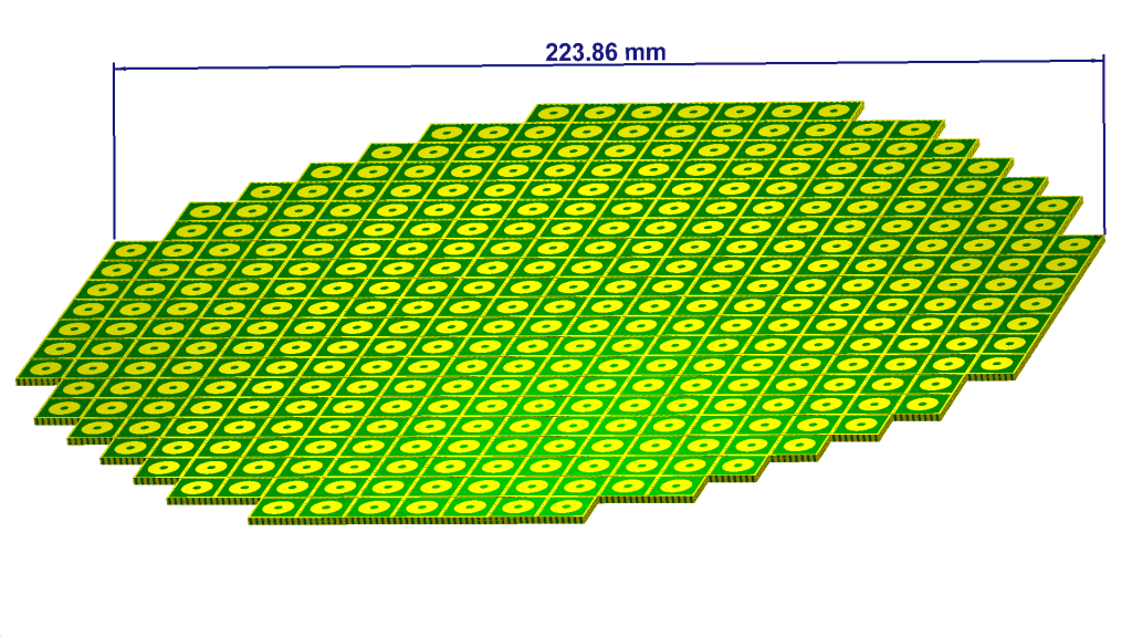
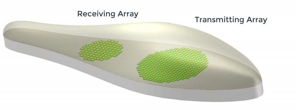
Now we have a unit element that is suitable for designing an infinite element array. But in reality, arrays consist of a finite number of elements (Figure 5). The outer most elements of the array contribute to non-periodic effects, hence as a rule of thumb, they are kept passive, i.e. they are not fed any power so that the unit element analysis is a better predictor of the actual array.
Modeling of the array was carried out with the help of Array Task, an intuitive tool which rapidly constructs an array of the desired shape and number of elements. It also allows us to select whether a given element is active or passive. In addition, it has a range of element excitation patterns which help define the shape of the main beam of radiation and allow electronic steering of the array.
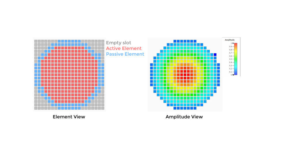
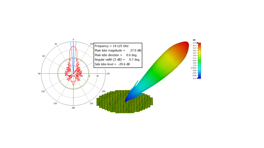
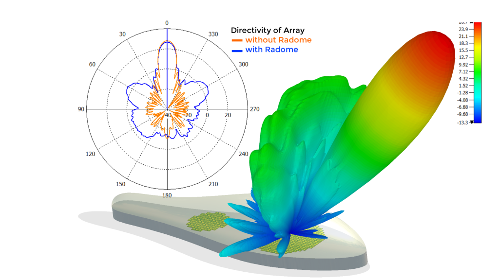
An elliptical shape was selected for the array with a Taylor excitation pattern. Time Domain simulations using the Finite Integration technique were carried out on the full array which allowed us to observe the radiation pattern of the array, as well as other antenna parameters such as gain, return loss, and total radiated power. We were able to achieve a good directivity of 27.9 dB and a side lobe level of -29.6 dB (Figure 7).
Similarly, another array was designed for receiving signals from the satellite.
Radome Design
Antennas are generally enclosed in a structure called the Radome which protects them from dust, rain, and ice (Figure 8). Careful design of radomes is important as they can significantly affect the performance of antennas.
A 3-layer sandwich radome was designed which consisted of two outer layers of quartz ( = 3.3, tanδ = 0.0004) enclosing a honeycomb structure which, in this frequency range, can be accurately simulated by modeling it as a bulk material with a single effective permittivity ( = 1.1). The full array was placed within the radome and the effect of the radome structure on the main beam gain and shape was studied using simulations.
Thus, we were able to successfully design and simulate a transmitting and receiving module of a SATCOM antenna system (Figure 9).
In conclusion, our easy-to-use tools help you to design phased arrays such as the SATCOM antenna in shorter time cycles. Such antennas are finding a range of usage in aircraft, such as Radar arrays for Weather Detection and Ground Based Tracking of Aircraft.
In the near future, satellite connectivity will provide a major upgrade to the aircraft Flight Recorder (Black Box). Instead of having to store all the flight data and cockpit voice recordings locally on an aircraft, antennas will be able to beam down all the data in real time via satellites, so that catastrophic events can be predicted well before they occur, thus making air travel even safer.
Please see our electronic communication and detection system performance solutions here.
SIMULIA offers an advanced simulation product portfolio, including Abaqus, Isight, fe-safe, Tosca, Simpoe-Mold, SIMPACK, CST Studio Suite, XFlow, PowerFLOW and more. The SIMULIA Learning Community is the place to find the latest resources for SIMULIA software and to collaborate with other users. The key that unlocks the door of innovative thinking and knowledge building, the SIMULIA Learning Community provides you with the tools you need to expand your knowledge, whenever and wherever.

Dr. Goyal is a Senior Technical Specialist, currently playing the role of simulation consultant in SIMULIA's Aerospace & Defense Industry growth team. He received his M.S. & Ph.D. degrees in Aerospace Engineering at Texas A&M University in August 2003 & December 2007 respectively. He is a recipient of American Institute of Aeronautics and Astronautics (AIAA) open topic graduate award in the year 2006. In academia, he has conducted extensive FAA, NASA & AFOSR funded research in tape laminated composites, textile composites & materials with complex microstructures. Since January 2008, he has been working with Dassault Systèmes SIMULIA Corp. where he has provided training & consulting services to SIMULIA’ s customers in various industries. Dr. Goyal has published several journal papers in highly reputed peer-reviewed international journals and has also reviewed scholarly articles of other researchers for leading journals in the area of Composites Materials.