The automotive industry has recently experienced a tremendous push towards electrification and all OEMs are planning to develop new electric cars. Especially hybrid (HEV) and battery electric vehicles (BEV) are developed and needed to fulfill ambitious CO2 emission targets faced by OEMs. This paradigm shift poses complete new challenges in the development process of these cars. One of these new challenges is the electromagnetic compatibility for such a vehicle. With the introduction of a high voltage system, and the flow of high currents feeding the drive train, novel concepts are required to ensure that the newly developed vehicles fulfill electromagnetic emission standards and human safety requirements.
Over the past years, electromagnetic simulation has proven that it can be of great value for the analysis and design of EMC compliant products. For EMC engineers, simulation became an important tool to complement measurements allowing to estimate the EMC performance of a product in the early design process. While measurements are needed to obtain certifications for a product, they can only be performed once a prototype is available. At this stage, the decision of the EMC concept needs to be already fixed and if changes are needed, they are leading to long re-design cycles. On the other hand, even if certification by simulation is currently not yet in place, being able to predict EMC performance at very early stages of the design process is the sweet spot for simulations.
In the past years, the EMC simulation was most heavily used at TIER 1 suppliers, for the system components delivered to an OEM. Typically the OEM defines the allowable emission limits of the components to the supplier. During the prototype phase, all components are assembled into the vehicle and EMC tests are run on the prototype. This approach is no longer possible for electric vehicles. Because in an electrically powered vehicle the components of the drive train are an integral part of the complete car, novel EMC concepts need to be included already at the very early stages of product development and can no longer follow the traditional approach where EMC was only of interest in the late design stages. One of the reasons why OEMs in the past were less using EMC simulation is the fact that the full vehicle is an extremely complex product and setting up simulation models and gathering all required data for simulation was not an easy task.
Dassault Systèmes offers the right solutions to tackle this complex problem: CST Studio Suite for the high fidelity electromagnetic simulation and the 3DEXPERIENCE platform for design, data management and collaboration. In today’s example, the workflow for the EMC simulation of a complete electric drive train will be presented. When creating simulation models for such complex scenarios, the connection of the 3DEXPERIENCE platform to CST Studio Suite by means of the POWER’BY connector can be of great benefit to the user. Geometrical simplifications that ensure an efficient simulation model can be performed natively on the 3DEXPERIENCE platform, saving precious time during model creation and meshing. Furthermore, the EMC simulation engineer always has access to the up-to date geometry as he is notified if changes to the CAD data by another department were performed.
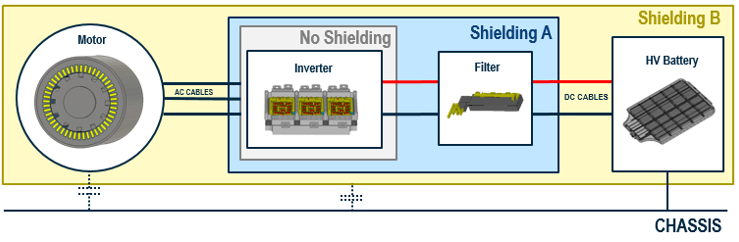
The main components of an electric drive train are: a battery to provide the electric current, a power electronics unit for controlling the motor, and the motor itself to create the mechanical torque (figure 1). Inside the power electronics unit, the inverter is the hearth of the system. Fed by the DC current from the battery, it is used to provide the right currents patterns to control the motor rotation. This is accomplished by so-called pulse width modulation (PWM). The current from the battery is switched in the inverter at rates much faster than the mechanical rotations, typically tenth of kHz. By applying this fast switching, the rotation of the motor can be accurately controlled at very high system efficiency. However, this switching is the main source of electromagnetic emission and care has to be taken to control this emission. This is typically accomplished by adding a filter between inverter and battery (see figure 1). All of the above components can be efficiently designed using simulation. However, once the complete system is integrated into the vehicle, two additional aspects need to be considered.
The first aspect is related to human safety: The high currents flowing through the power train are a source of magnetic fields. The exposure of human body to a time varying magnetic field has to be limited according to standards (for example ICNIRP) enforced by regulatory bodies. The second aspect is the parasitic coupling of the electromagnetic fields to the chassis of the car. Such a coupling can lead to a resonant current flow in the chassis that leads to failures in EMC testing, even when the system was passing the test in laboratory environment. The common strategy at the OEM side to countermeasure these aspect is to apply (electromagnetic) shielding to the powertrain. However, shielding is adding cost and weight to the vehicle. Thus, an optimized shielding strategy is an important factor in terms of cost and power efficiency and also in terms of product safety.
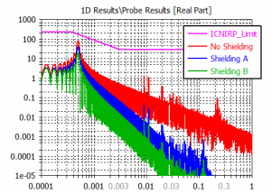
In our simulation we have compared three scenarios. In scenario 1, all components are placed into their respective metallic enclosures, but there is no common shielding and also all cables are unshielded. In scenario 2, a common enclosure was added around the inverter and the filter, while in scenario 3 all components are shielded. The excitation in the simulation model is performed inside the inverter and the (frequency dependent) coupling from the inverter to the battery is calculated. This approach allows to analyze the coupling for a broad range of possible operating frequencies of the drivetrain.
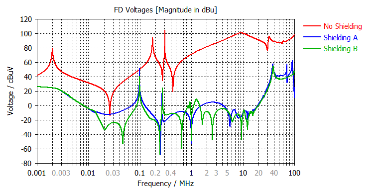
The results of the simulation are depicted in figure 3. As expected, the emission from the inverter to the battery is the highest in the scenario without additional shielding. A very interesting result is the fact that the additional shields added in case B do not improve the emission spectrum significantly. If the emission levels are satisfactory already in case A, then the addition shielding of case B does not need to be implemented, saving time and weight. If the emission levels are still too high, then a re-design of the shielding strategy is necessary.
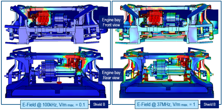
One of the strengths of simulations is the possibility to visualize electric and magnetic fields that are not visible to the human eye. For both shielded cases, the emission exhibits peaks at 100 kHz and 37MHz as already concluded from figure 3. In figure 4 we have plotted the electric field at these frequencies. We can clearly conclude that both resonances are a result of the geometry of the engine bay, where current loops can be formed through the chassis components. Obviously these loops are not present in a laboratory set-up and occur only once the complete drivetrain has been mounted inside the vehicle. Estimating these frequencies without a fully assembled prototype of the vehicle is only possible by using simulation.
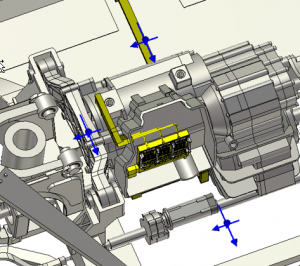
For the analysis of human safety, we have placed magnetic field probes inside the engine bay. They are visualized by blue arrows in figure 5. The ICNIRP limit for exposure to magnetic fields is frequency depended as shown by the magenta line in figure 6. In order to calculate the correct spectrum of the magnetic field, a PWM signal was applied to the inverter. A PWM frequency of 10 kHz was used and the sine frequency to drive the motor was chosen to 500 Hz. Because the main current contribution is from the 500 Hz signal, we also observe the highest magnetic field at this frequency. All probes in this example are below the INCIRP limit, but not too far away from the this limit at 500 Hz. As only a few probe positions were considered in this example, it is advisable to continue the study including more positions.
In today’s blog entry we were able to show you how electromagnetic simulation can be used to predict the EMC and dosimetry behavior for the next generation of electric vehicles. This aspect of product design is very different when comparing ICE and electric vehicles and Dassault Systèmes is is able to offer you all the tools needed for the simulation of the electric drivetrain.
SIMULIA offers an advanced simulation product portfolio, including Abaqus, Isight, fe-safe, Tosca, Simpoe-Mold, SIMPACK, CST Stuido Suite, XFlow, PowerFLOW and more. The SIMULIA Learning Community is the place to find the latest resources for SIMULIA software and to collaborate with other users. The key that unlocks the door of innovative thinking and knowledge building, the SIMULIA Learning Community provides you with the tools you need to expand your knowledge, whenever and wherever.

Andreas is a senior solution consultant for electromagnetic simulation at Dassault Systèmes in Darmstadt, Germany. After receiving his PhD in numerical electromagnetics from the Darmstadt University of Technology in 2007 he joined CST which later became a part of Dassault Systèmes. His main interest lies in the simulation of electromagnetic compatibility of electronic systems, ranging from high-speed to power electronics.