
This post was originally published on January 22, 2019.
The number of electronic components in the average car is increasing and smart vehicles are a major driver of growth in the automotive market. Designing an electronic system in isolation always poses a challenge to the electronic engineer, but connecting multiple systems creates additional challenges. Communication between these electronic systems based on high-performance standards is key for fast and proper data transfer.
For example, modern electronic systems like infotainment and advanced driver-assistance systems (ADAS) require very high bandwidth for video streaming. The traditional vehicle bus protocols like Controller Area Network (CAN) are not able to provide enough bandwidth. Automotive Ethernet is one of the leading proposals for an upgrade.
BroadR-Reach® is a point-to-point Ethernet Physical Layer standard for automotive applications, allowing full-duplex communication between two devices over an unshielded twisted wire pair at 100 Mb/s, with plans to increase it up to 1000 Mb/s. This high bitrate means that the system is susceptible to high-frequency interference and, at frequencies above 1 MHz, the BroadR-Reach automotive Ethernet carries a much higher spectral content than the CAN bus. Designers need to be aware of this and apply the proper techniques to mitigate emissions at these higher frequencies. Making BroadR-Reach Ethernet compliant with automotive EMC requirements is a challenging task.
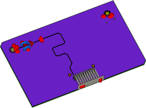
Traditionally, EMC testing has been heavily reliant on measurements with physical prototypes, which can lead to multiple troubleshooting iterations with high corrective costs and a delayed time to market. Virtual prototyping with electromagnetic simulation allows potential interference issues to be identified earlier in the design process, potentially saving time and money. The examples presented in this whitepaper are all based on the coupling of the full wave 3D model to a circuit simulation.
Read the full whitepaper here.
Want to find out more? Register for free membership and check out our eSeminars on automotive applications:
- EMC Simulation of Automotive Ethernet
- Simulation and Resolving EMC/EMI Issues in Electric Vehicles
- Electromagnetic Simulation for Tomorrow’s Vehicles
SIMULIA offers an advanced simulation product portfolio, including Abaqus, Isight, fe-safe, Tosca, Simpoe-Mold, SIMPACK, CST Studio Suite, XFlow, PowerFLOW and more. The SIMULIA Learning Community is the place to find the latest resources for SIMULIA software and to collaborate with other users. The key that unlocks the door of innovative thinking and knowledge building, the SIMULIA Learning Community provides you with the tools you need to expand your knowledge, whenever and wherever.

Matthias Tröscher is a SIMULIA Senior Business Development Executive, focusing on EM simulation in the automotive industry. He studied physics at the Technical University in Munich and received his doctorate in 2000 from the Johannes Kepler University Linz for his work on radar warning systems carried out for BMW. Matthias Tröscher has worked at CST since 2009 before he joined DS SIMULIA in 2019. He is Senior Member of the IEEE EMC Society, Vice Chairman of the IEEE German EMC Chapter and Chair of the IEEE Technical Committee TC-9 for Computational Electromagnetics.