
The efficient simulation of periodic structures and their application in radome design are the focal points of today’s blog. I will discuss the workflow that brings us from an individual element to the finite array as well as suitable approaches to simulate them.
Periodic structures- unit cells
Periodic structures often exhibit interesting electromagnetic behaviors. Metamaterials, artificial magnetic conductors, and Frequency selective surfaces (FSS) are few examples of applications based on periodic structures. The latter can be used as a potential approach to obtain customized frequency filtering radomes for antenna applications [1-2].
CST Studio Suite can tackle the periodic structures using two general approaches. One is eigenvalue problems for which Eigenmode Solver should be used to obtain standard results such as dispersion diagrams including bandgaps and light line curves [3]. The second approach is based on the Floquet theorem in which different so-called “Floquet modes” for the desired periodic structures are considered and excited. CST Studio Suite finds transmission and reflection between the Floquet modes and other ports (excitations) existing in the model.
Unit _Cell simulation set-up
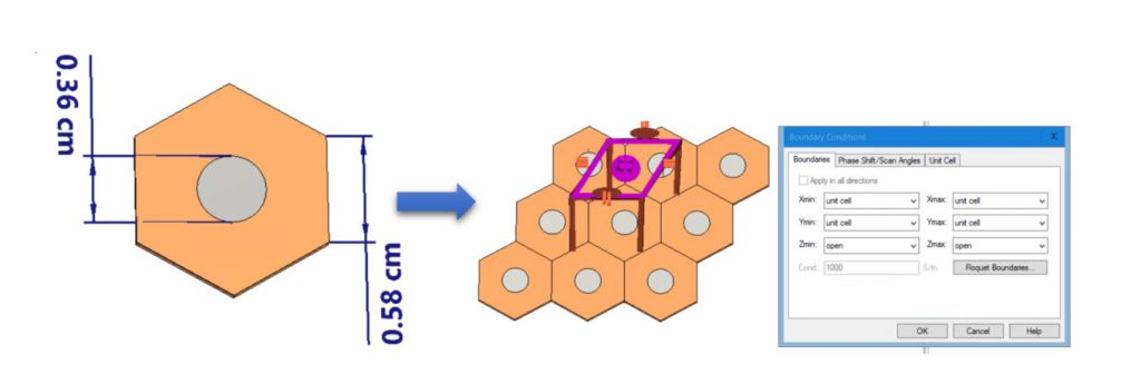
To start the FSS design, I consider a hexagonal lattice based unit cell of a dielectric filled by a metallic disk at center as depicted in Figure 1. It is simulated in CST Microwave Studio using the Frequency Domain Solver (F-solver) and Unit cell boundary condition (Floquet mode analysis).
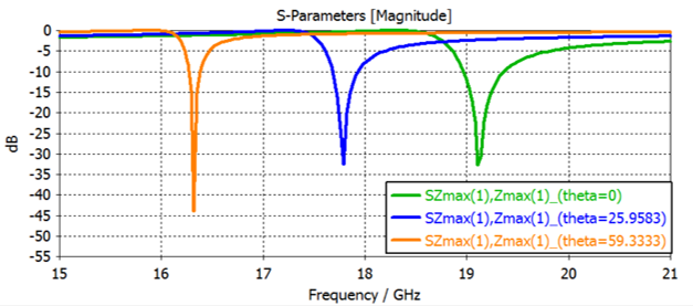
As the reflection coefficient of the unit cell suggests (Figure 2a), there is a frequency, namely at 19.12GHz, in which the fields can mainly penetrate through the periodic structure while there is a relatively huge reflection at other frequencies. Thus, it is safe to say that we have a kind of band pass filter.
Don’t miss the October 6th SIMULIA Tech Talk on this topic!
The default setting of the unit cell boundary condition delivers the simulation results for normal incidence only. However, it is important to evaluate the electromagnetic behavior of the infinite structure at different incident angles. This can be easily achieved by performing a parameter sweep over the scan angle parameter provided in the unit cell boundary condition window. Figure 2a shows the reflection coefficient of the proposed unit cell under three different incidence angle of incoming plane wave. Figure 2b shows the electric field behavior at the pass band and notch band frequencies, accordingly.
Finite size FSS based radome
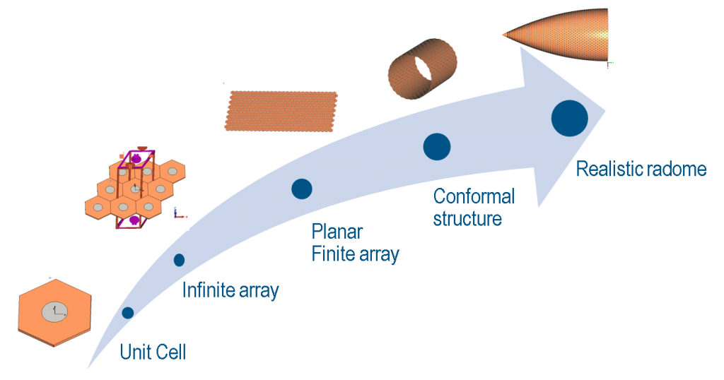
Although simulating based on infinite periodic topology is always a good starting point to figure out how the FSS works, its performance should be checked under finite size FSS radome assumptions. Figure 3 shows the complete flow from an infinite array to a realistic radome structure.
Three approaches to simulate FSS based radomes
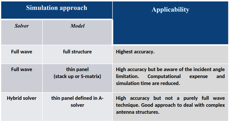
The question that arises here is: which solver(s) or material model should one use? To address this question, I introduce three approaches in the following:
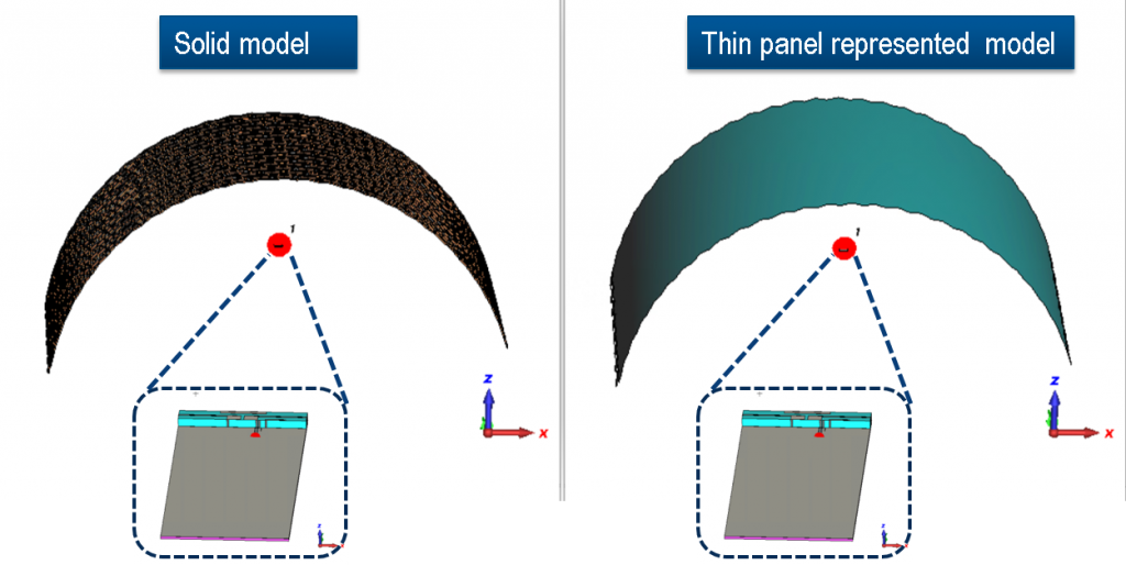
The first approach is to use full wave solvers and include all geometrical details of radome and antennas. Although this approach would be the most complete approach, it would also be the most computationally expensive one. However, CST Studio Suite offers several ways to accelerate the simulation time such GPU hardware acceleration, distributed computing, MPI, etc. for more information; please see the SIMULIA website [4].
The second approach is to use full wave solvers while representing the radome with the help of compact material modeling known as thin panel material in CST Studio Suite. Thin panel materials would be defined either based on stack-up layers of materials or scattering matrix data. The complex geometry of the FSS is replaced by continuous and compact represented materials, which is computationally favorable. It should be noted that thin panel is an approximated model based on plane wave and one incidence angle (normal incidence for the type of stack up and customized by user for the type of S-matrix).
The third approach is to separate the antenna from the radome simulations, perform each in the best suited solver, and establish the link between these simulations through field sources. This Hybrid Solver approach enables us to use, for example, the Asymptotic Solver (A-solver) in which a ray-tracing physical optics (PO) based algorithm is being employed for simulating the radome whereas transient solver is used to simulate antenna. It makes the overall simulation computationally less expensive. Furthermore, the A-solver supports thin panel materials for which Fresnel reflection and transmission table for different incident angle could be defined. This feature improves the result accuracy of A-solver simulations.
Conformal FSS-type radome simulation results:
To show a proof of concept, I have simulated a half-cylindrically bended FSS based radome. An F-inverter antenna with omnidirectional pattern was used as the source antenna.
The full wave simulations, including the conformal finite size FSS and antenna, were conducted using the time domain Transmission Line Matrix (TLM) solver. The animated visualizations in Figure 5-7 show the electric field for f=15, 25, 19.2 GHz, respectively.
Notch-Band Frequencies:
For the notch-band frequencies (f=15 GHz, f=25 GHz), full model and thin panel approaches have been only investigated and plotted. The field animation of figures 5 and 6 show the almost perfect agreement between these two approaches for the structure under study.
Pass-Band Frequencies:
It is interesting to compare the simulation results for the pass band frequency – namely 19.2 GHz – as well. Since not all the radiated waves from the antenna hit the radome surface with a perpendicular angle, multiple reflections are generated simply because the reflection and transmission properties of the FSS unit cell changes with the incident angle (see figure 2a). This leads to standing wave behavior or cavity-like resonances. This effect can be seen very well in Figure. 7a. In addition, some surface resonances are generated that can be only captured using full wave approach as shown in the same Figure. The thin panel (S-matrix type) model, shown in Fig. 7b, is unable to deliver the same result compared to full model simulations. The reason lies on this fact that the thin panel material can only be defined based scattering matrix of one incident angle (we used normal incidence in this case) and therefore it does not include the reflection and transmission for non-normal incident angles.
Last, we used the Hybrid Solver approach to simulate the proposed model. A bi-directional coupled TLM and asymptotic solver is used to simulate antenna and radome models accordingly. Two solvers communicate through near field source and the relative residual error decreases below an acceptable threshold over a few iterations. It can be noted that the hybrid solver approach is also able to capture the standing-wave field behavior similar to the full model approach as shown in Fig. 7c.
Conclusion
Conformal and frequency selective surfaces being used as radomes create a complicated electromagnetic environment that demand accurate and reliable simulations. In this study, three approaches were investigated starting from full-wave complete model simulation, full-wave and compact model simulation and hybrid solver simulations. Table. 1 summarizes the above-discussed approaches and their applications in FSS radome design. The author hopes that this short article could give CST Studio Suite users deeper insights to select the most suitable solver/approach for their antenna/radome simulations.
All the geometry creation, handling, simulations have been performed with CST Studio Suite. Transmission line matrix (TLM) solver, asymptotic solver, frequency domain solver, and hybrid solver workflow were the solvers that have been used in this study [4].
CST Studio Suite offers different approaches to strike a good balance between accuracy and simulation times for different types of radomes.
References:
- Jackson, John David. “Classical electrodynamics.” (1999): 841-842.
- Joannopoulos, John D., Steven G. Johnson, Joshua N. Winn, and Robert D. Meade. “Molding the flow of light.” Princeton Univ. Press, Princeton, NJ (2008).
- https://www.linkedin.com/pulse/band-diagram-analysis-cst-studio-suite-approach-reza-hosseini/
- Dassault Systèmes, https://www.3ds.com/simulia/.
Discover extensive Electromagnetics resources and connect with other Electromagnetics experts in our SIMULIA Community.

SIMULIA offers an advanced simulation product portfolio, including Abaqus, Isight, fe-safe, Tosca, Simpoe-Mold, SIMPACK, CST Studio Suite, XFlow, PowerFLOW and more. The SIMULIA Community is the place to find the latest resources for SIMULIA software and to collaborate with other users. The key that unlocks the door of innovative thinking and knowledge building, the SIMULIA Community provides you with the tools you need to expand your knowledge, whenever and wherever.

Reza Hosseini is a SIMULIA Industry Process consultant, where he currently works on providing solutions for the electromagnetic challenges of SIMULIA EMAG customers interested in high frequency, microwave/antenna, optical, RF and EMC applications through a variety of industries such as Transportation & Mobility Suppliers, Aerospace & Defense, etc. Reza Joined CST in 2018 as an application engineer and later Dassault Systèmes via CST’s acquisition. Reza holds a PhD in Electrical Engineering, Silicon Photonics, from Dresden University of Technology (TU Dresden) in Germany. He had been involved in different simulation and experimental high frequency and photonics projects covering the broad range from component level up to system level.