By Monika Balk
Overview
This blog post will demonstrate collaborative antenna design using the example of a 5G small cell antenna array. The design of any high-tech product typically involves many different departments, often spread across many locations. The additional overhead introduced by separate working environments costs time and delays in product rollout. In addition, working in silos makes it very difficult to keep a global overview of the different product candidates and the required physical and virtual tests. We will show how the 3DEXPERIENCE platform facilitates collaboration and helps to improve efficiency in product lifecycle management, requirements engineering, and analysis of simulation results.
In addition to the short video demonstrating the collaboration on the 3DEXPERIENCE platform that is embedded here, there is also an extended version hosted in the SIMULIA community.
The Scenario: Designing a 5G small cell antenna array
The antenna department has designed a 5G small cell antenna array with the correct radiation characteristics. The designer creates different housing variants for the given antenna array, which have to be validated for aerodynamic and thermal performance. The goal is to fulfill temperature requirements while simultaneously maintaining the electromagnetic behavior, and requires both electromagnetics and fluid dynamics simulation.

How to improve collaboration?
We all know the established way of working by sending emails to a list of addresses, where information can get lost and is hard to find again. The 3DEXPERIENCE platform offers the possibility to communicate in web-based communities, so everyone involved in a task has instantaneous access to the same information.
Check out the full presentation on the SIMULIA Community!
Furthermore, with the project management tool, the project manager and involved collaborators can keep an overview of the progress and timeline of tasks. The tasks can hold additional information such as 3D models or simulation objects. When assigning or finishing the project, engineering deliverables containing all information related to the design and simulation are accessible from the project. In addition, attaching objects to a task automatically gives access rights to the assignee. In summary, the platform serves as the single source of truth, removing lengthy search processes and saving time.
Requirements Engineering
An important step in product development is capturing and verifying product requirements. The 3DEXPERIENCE platform offers requirement definitions from high-level descriptions down to actual parameters. Similarly, it is possible to trace the impact of the requirements from the functional and logical layers of the product down to the physical implementation. This reveals dependencies and can identify unconsidered requirements.
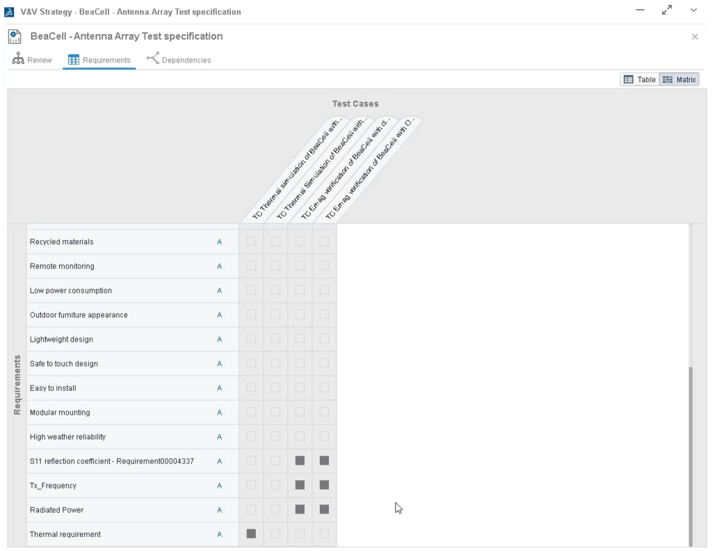
To avoid late-stage failures or unsatisfied customers, the verification & validation team needs to test the product versus requirements. This can be a virtual or physical test. However, it is important to have a sufficient number of tests, without unnecessary duplicates. The Test Manager role is of great help here, as it gives visual feedback in form of a matrix showing requirements assigned to a test case and identifying untested ones. The test cases can hold additional data, such as simulation files, documentation of test procedures, and more. Considering that verification and validation are a major part of product development, covering all necessary tests while simultaneously avoiding unnecessary ones, leads to better efficiency and increased profitability.

Requirements are living objects on the 3DEXPERIENCE platform with their own life cycle, in contrast to former inflexible static approaches. This enables them to be adapted to new situations and is especially helpful for change management.
Comparing and managing product variants
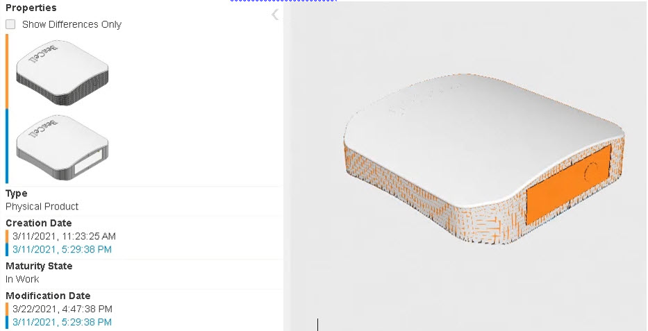
In this example, the designer creates two candidates for the 5G small cell antenna: One with a closed housing and one with openings at the bottom and top edges of the enclosure. All stakeholders can review the different variants on the 3DEXPERIENCE platform using the product structure editor, a web-based application showing the Bill of Materials (BOM). The shown service BOM software can even include geometry and components from different sources (including CATIA, Solidworks, Altium, and others).
A Compare Tool highlights the product’s differences, such that everyone quickly understands them. This supports fast and easy communication between team members.
During the development, it is important to capture and clarify the status of the different candidates. Therefore, different branches represent modifications of the baseline model, and in the end, the best-performing one will be released.

How to verify performance using simulation?
In this example, the thermal behavior of the two housing cases is evaluated with the native Fluid Dynamics Engineer role. The electromagnetic results are obtained with CST Studio Suite, which connects to the platform. Web-based platform apps then visualize the results, so that engineers can communicate them to non-experts in their team.
In this example, the thermal simulation uses a steady-state Reynolds-Averaged Navier-Stokes (RANS) computational fluid dynamics analysis, and the electromagnetic simulation uses a 3D full-wave transient analysis based on the Finite Integration Technique (FIT).
The results show that the closed housing violates the temperature requirement, in contrast to the open one. Both variants maintain the electromagnetic behavior as intended.
Finally, to judge the different candidates, the Performance Trade-Off app lists key performance indicators and highlights the best candidate. Threshold values help to ensure compliance with regulatory standards. This visual feedback is especially helpful if the number of variations increases. Since everything is available in the same web-based environment, the team decides quickly on the best release candidate.
In the next step, it would be also easy to send the corresponding model to manufacturing, since the 3DEXPERIENCE platform provides a connection between simulation results and CAD geometry. This avoids error-prone searching in simulation file folders and speeds up the product rollout.

It is possible to automate the design space analysis and connect the different physics using Process Composer. Process Composer can directly access the parameters defined in the geometry and in the different physics scenarios to set up the process flow. This enables multi-discipline simulation and avoids manual parameter handover, which in the end reduces errors and increases efficiency. However, this part is not covered in the video.
Collaboration on the 3DEXPERIENCE platform
Collaboration is an important part of current High-Tech device development. The 3DEXPERIENCE platform helps by providing an environment with:
- End-to-end traceability from product service BOM to simulation structures and results
- End-to-end traceability from requirement to tests
- Web-based collaboration tools for example communities, result viewer, and test management
Improved collaboration saves time and enables interdisciplinary communication. This can boost innovation and early detection of potential failures, such that finally, the development of products gets more efficient.
Want to see more? Visit the community for the entire presentation, here.

SIMULIA offers an advanced simulation product portfolio, including Abaqus, Isight, fe-safe, Tosca, SIMPACK, CST Studio Suite, XFlow, PowerFLOW, and more. The SIMULIA Community is the place to find the latest resources for SIMULIA software and to collaborate with other users. The key that unlocks the door of innovative thinking and knowledge building, the SIMULIA Community provides you with the tools you need to expand your knowledge, whenever and wherever.

