
This article was authored by Mathew Weglarz, Principal Engineer at Ariens Co., and Tim Hunter, Ph.D., President of Wolf Star Technologies, LLC.
 Ariens is a manufacturer of high end and industrial zero turning radius mowers. Ariens faced a redesign challenge to an existing line of zero turning radius mowers. The mower has a steel engine plate positioned below the seat on the mower. Bolted to the engine plate are the transmissions and the engine. The transmissions were running too hot and it was determined that the engine plate needed modification to provide increased access to cooling air. The engine plate was redesigned to improve airflow to the transmissions, but still maintained the required structural integrity. To tackle this challenge, Ariens engaged Wolf Star Technologies to assist with the redesign and to provide decision ready data to the team.
The mower is subjected to a proving ground course consisting of a very rough profile and must perform several maneuvers with the mowing equipment engaged. This creates an extremely complex profile of loading that cannot be analyzed by traditional means. Conventionally, the structure would be fitted with accelerometers. From the acceleration data, loads would be determined. This is very difficult in practice as the masses associated with those accelerations are difficult to determine. Alternatively, the structure could be fitted with load cells in key areas. In many cases it is difficult to capture all the load cases acting on the structure in this manner.
Since traditional methods are impractical, Wolf Star Technologies employed their True-Load software to turn the engine plate into a load transducer to determine the operating forces acting on the structure induced by the complex loading profile. This loading profile in turn was used to drive the redesign process on the engine plate.
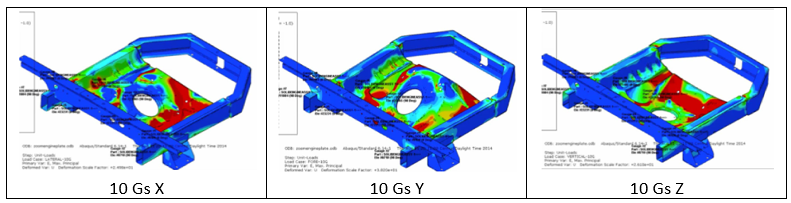
The first step of the process is to apply unit loads to the FEA model. It was determined that the appropriate unit load cases would be 10Gs in X, 10Gs in Y and !10Gs in Z directions (Figure 1). This would be able to characterize any arbitrary excitation of the structure.
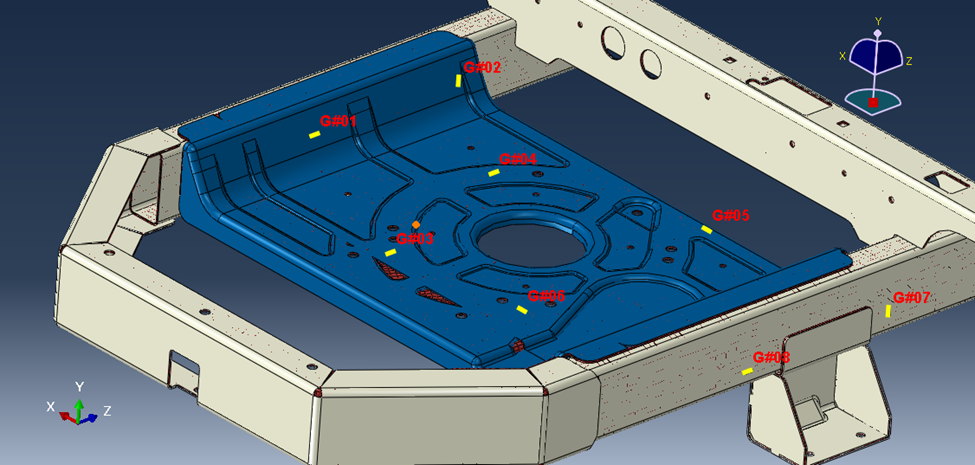
From these three unit load cases, True-Load determined that there were 8 optimal strain gauge locations on the structure (Figure 2). Once applied to the structure, these 8 strain gauges would be sensitive to the entire loading profile.
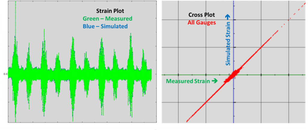
Strain Gauges were applied on the structure per the True Load specified locations. The mower was driven over the proving ground and strain data was collected. True-Load processes the strain data through the True-Load/Post-Test module to calculate the operating forces from the strain data. True-Load/Post-Test automatically creates correlation plots showing the simulated strains at the gauges plotted against the measured strain from the proving ground (Figure 3).
Ariens had attempted the first redesign using their internal engineering guidelines for engine plates. The first prototype was on shaker test when Ariens started the project. The unit had failed at 1200 hours on a 10,000-hour shaker test. The loading data was collected, and the initial failed model was run in fe-safe® using the loads calculated from True-Load. The loads from True-Load together with fe-safe® durability calculations predicted a life of 1000 hours. This is a perfect correlation in the fatigue world and revealed that the loads determined from True-Load were correct.
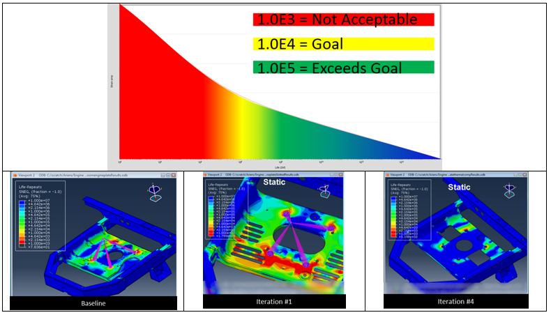
In conjunction with the engineers at Ariens, we rapidly went through five design iterations of configurations. These iterations included configurations with varying sheet metal thickness, material, and hole patterns. (Figure 4). All iterations used the True-Load determined loads and fe-safe® to analyze the structural integrity. The fifth iteration provided the necessary airflow and better durability than the initial design.
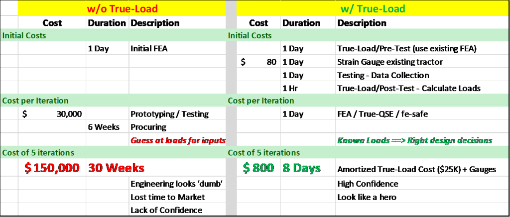
The engineers at Ariens concluded that they were able to reduce cost and decrease time to market. Figure 5 summarizes the cost and time efficiency of using True-Load in the design cycle. Ariens was able to increase their speed to market by 25x and reduce costs by orders of magnitude using Abaqus, fe-safe® and the True-Load software by Wolf Star Technologies. True-Load was able to calculate operating forces from strain measurements on their proving grounds. These strain correlated loads drove design changes in a mission critical product update. This efficiency improvement in product development has 5x implications on reduction of the environmental footprint from product development: reduced raw material, reduced energy.
Ariens was able to hit the triple bottom line by implementing True-Load with Abaqus and fe-safe® to deliver products to market faster and more efficiently. If an engineer can determine the actual stresses acting on their structure, designs can be delivered quickly and on time using the advanced simulation tools provided by the Abaqus, fe-safe® and True-Load platform.
SIMULIA offers an advanced simulation product portfolio, including Abaqus, Isight, fe-safe, Tosca, Simpoe-Mold, SIMPACK, CST Studio Suite, XFlow, PowerFLOW and more. The SIMULIA Learning Community is the place to find the latest resources for SIMULIA software and to collaborate with other users. The key that unlocks the door of innovative thinking and knowledge building, the SIMULIA Learning Community provides you with the tools you need to expand your knowledge, whenever and wherever.

Clare Scott is a SIMULIA Creative Content Advocacy Specialist at Dassault Systèmes. Prior to her work here, she wrote about the additive manufacturing industry for 3DPrint.com. She earned a Bachelor of Arts from Hiram College and a Master of Arts from University College Dublin. Clare works out of Dassault Systèmes’ Cleveland, Ohio office and enjoys reading, acting in local theatre and spending time outdoors.