
For each fault I have selected Edit Points, to give a different throw and dip at each point along the fault string.
Be sure to check that your fault blocks are tidy with no holes or irregular triangles. Duplicated points in the fault string can sometimes cause holes in the fault blocks.
The last steps in the 3D Fault Modelling Process will be continued in our next blog post – watch this space! Check out Part 1 of this series or How to Model a 2D Fault.
– In Minex 6.5.1 if ‘ovrw’ is selected in the above table, then the throw, dip and azimuth values will be used from the table above. This option should be selected when applying a single dip and throw to the entire fault length. – The other option ‘auto’ in the Spec column will allow the user to click Edit Points and define individual dip and throws, point by point along the fault string (optional). Note that in older versions of Minex ‘ovrw’ and ‘auto’ work the opposite way around.
The throws and dip values entered into the above table should be written as follows, depending on the type of fault you wish to model. When looking the down the fault string, in the string direction (direction string was digitized), the following will apply:
– Negative throw value will produce a normal fault and a positive throw value will produce a reverse fault;
– Negative dip value will dip the fault plane towards the left-hand side of the fault string;
– Positive dip value will dip the fault plane towards the right-hand side of the fault string.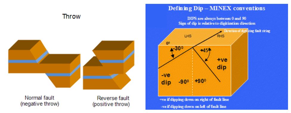 In this example, I have set up the Fault Definitions tab as follows:
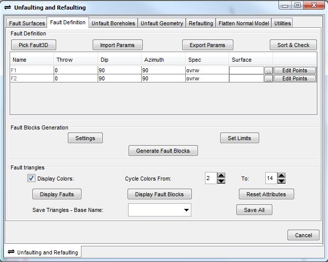
For each fault I have selected Edit Points, to give a different throw and dip at each point along the fault string.
Be sure to check that your fault blocks are tidy with no holes or irregular triangles. Duplicated points in the fault string can sometimes cause holes in the fault blocks.
The last steps in the 3D Fault Modelling Process will be continued in our next blog post – watch this space! Check out Part 1 of this series or How to Model a 2D Fault.
- First, display your 3D fault strings in the graphics window and navigate to the SeamModel > Unfault/Refault function and the Fault Definition tab.
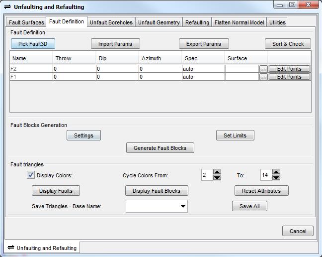
- Select Pick Fault3D and click on the fault strings in the graphics window. If your faults intersect, it is critical to select the faults in the correct sequence, from oldest to newest. If none of the faults intersect, selection order is not critical. Right click on your mouse to stop string selection. The table will then populate with the faults selected, for example:
This table must be filled in one of two ways:
– In Minex 6.5.1 if ‘ovrw’ is selected in the above table, then the throw, dip and azimuth values will be used from the table above. This option should be selected when applying a single dip and throw to the entire fault length. – The other option ‘auto’ in the Spec column will allow the user to click Edit Points and define individual dip and throws, point by point along the fault string (optional). Note that in older versions of Minex ‘ovrw’ and ‘auto’ work the opposite way around.
- Additionally, if a triangulated fault plane has been prepared then this can be selected under the Surface option in the above table (optional).
The throws and dip values entered into the above table should be written as follows, depending on the type of fault you wish to model. When looking the down the fault string, in the string direction (direction string was digitized), the following will apply:
– Negative throw value will produce a normal fault and a positive throw value will produce a reverse fault; – Negative dip value will dip the fault plane towards the left-hand side of the fault string; – Positive dip value will dip the fault plane towards the right-hand side of the fault string.
In this example, I have set up the Fault Definitions tab as follows:For each fault I have selected Edit Points, to give a different throw and dip at each point along the fault string.
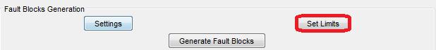
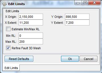
- Select auto for the Spec and Edit Points with dips and throws, then click Set Limits.
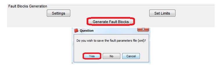
- After you have set your limits and clicked OK, select Generate Fault Blocks. If prompted, save the fault parameter, which will save an .xml file such as “3DFault_Parameters.xml“. This can be re-imported by selecting Import Params.
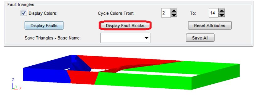
- Now, you can view your fault blocks by selecting Display Fault Blocks:
Be sure to check that your fault blocks are tidy with no holes or irregular triangles. Duplicated points in the fault string can sometimes cause holes in the fault blocks.
The last steps in the 3D Fault Modelling Process will be continued in our next blog post – watch this space! Check out Part 1 of this series or How to Model a 2D Fault.
Earlier in the week, we covered the first part of modeling a 3D fault in Minex, specifically how to create a fault trace. Today we will look at how to use Fault Definition.
- First, display your 3D fault strings in the graphics window and navigate to the SeamModel > Unfault/Refault function and the Fault Definition tab.
- Select Pick Fault3D and click on the fault strings in the graphics window. If your faults intersect, it is critical to select the faults in the correct sequence, from oldest to newest. If none of the faults intersect, selection order is not critical. Right click on your mouse to stop string selection. The table will then populate with the faults selected, for example:
This table must be filled in one of two ways:
– In Minex 6.5.1 if ‘ovrw’ is selected in the above table, then the throw, dip and azimuth values will be used from the table above. This option should be selected when applying a single dip and throw to the entire fault length. – The other option ‘auto’ in the Spec column will allow the user to click Edit Points and define individual dip and throws, point by point along the fault string (optional). Note that in older versions of Minex ‘ovrw’ and ‘auto’ work the opposite way around.
- Additionally, if a triangulated fault plane has been prepared then this can be selected under the Surface option in the above table (optional).
The throws and dip values entered into the above table should be written as follows, depending on the type of fault you wish to model. When looking the down the fault string, in the string direction (direction string was digitized), the following will apply:
– Negative throw value will produce a normal fault and a positive throw value will produce a reverse fault; – Negative dip value will dip the fault plane towards the left-hand side of the fault string; – Positive dip value will dip the fault plane towards the right-hand side of the fault string.
In this example, I have set up the Fault Definitions tab as follows:For each fault I have selected Edit Points, to give a different throw and dip at each point along the fault string.
- Select auto for the Spec and Edit Points with dips and throws, then click Set Limits.
- After you have set your limits and clicked OK, select Generate Fault Blocks. If prompted, save the fault parameter, which will save an .xml file such as “3DFault_Parameters.xml“. This can be re-imported by selecting Import Params.
- Now, you can view your fault blocks by selecting Display Fault Blocks:
Be sure to check that your fault blocks are tidy with no holes or irregular triangles. Duplicated points in the fault string can sometimes cause holes in the fault blocks.
The last steps in the 3D Fault Modelling Process will be continued in our next blog post – watch this space! Check out Part 1 of this series or How to Model a 2D Fault.

Ross is a qualified Resource Geologist with 9 years' industry experience in database management, geological modeling, grade control, geostatistics, resources estimations and process mapping. Since joining GEOVIA, Ross has worked with and assisted mining clients across Europe, Middle East and Africa. His commodity experience includes gold, copper, lead, zinc, iron, coal, bitumen and various industrial minerals. He regularly delivers support, training and consultancy services in GEOVIA Surpac, GEOVIA Minex, GEOVIA MineSched and various roles on the 3DEXPERIENCE Platform. Ross is based in Coventry, UK.