
Within GEOVIA Surpac™, the graphics point and line snap behaviours are now sensitive to the virtual strings created to represent the line of intersection between a Plane and solids/surfaces. The improved flexibility benefits the BEARING AND DISTANCE function, available to all Surpac users, by letting you use any combination of real and virtual points to calculate the bearing and distance between positions in graphics window.
These strings are referred to as “virtual” because they don’t really exist. If you save a string file these strings won’t appear in it. You can save these virtual strings if you need to by using the SAVE SECTION TO STRING FILES function which is found on the Planes → Save section to string files menu item.
Try it using these simple steps:
-
-
-
- Open a DTM of a solid or a surface
- Open the Planes panel and press the Quick Planes button in the Planes panel to invoke the Quick Planes function then create an oblique plane that intersects with the triangulated mesh.
- Press the 2D/3D Planes toggle button in the Planes panel to lock Surpac into a 2D view.
- Press the Draw triangulations as triangles or polylines toggle button in the Planes panel to just display the line of intersection.
- Run the BEARING AND DISTANCE function by typing the “BD” shortcut into the command window.
-
-
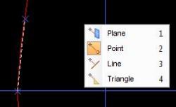
- While using the BEARING AND DISTANCE function, Surpac will display either “Select the setup point” or “Select the foresight point” to advise you pick the points between which the bearing and distance will be calculated. Whenever these prompts are displayed, you can press the right mouse button to display the snap context menu to change the snap mode. Note how the icon for the active snap mode is highlighted. The active snap mode is also indicated on the snap mode toolbar button.
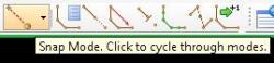
Looking to better understand the behavior for each of the snap modes? Here is a quick overview.
Plane – The location of mouse cursor on the active plane is used. Point – The real or virtual point closest to the cursor location is used. The rubber band feedback line snaps to the point as you move the mouse. Line – A position on the real or virtual string closest to the cursor location is used. The rubber band feedback line snaps to the string as you move the mouse. Triangle – A position on the triangle beneath the cursor location is used when you press the mouse button. In this case it’s not possible to give rubber band feedback.
With Point snap mode enabled, these virtual strings can be used by any Surpac function that requires you to digitise a new location. While this might seem like a subtle change, it makes a significant improvement to the flexibility of working in Surpac’s 3D graphics design window.
When mining companies seek to increase mine productivity, they turn to Dassault Systèmes for technology and services. It is home to world-renowned and award-winning mining solutions and to industry thought leaders who are pushing the boundaries of what’s possible in mining, through the GEOVIA brand. The largest global supplier of mining software, GEOVIA delivers comprehensive solutions in all major mining centers in more than 130 countries at over 4,000 sites.