

- First, create the oblique plane that all your subsequent parallel planes will be based off.
Use Planes > Quick planes to access the form below. The plane corridor is the viewing corridor width either side of the plane. As you will be creating 1m wide parallel planes in this example, a corridor of 0.5 away and toward will enable you to cycle through the planes and view the entire object.
- When the form is applied, Surpac will ask you to “click and drag to define the cutting plane”. It is important to drag the line in the correct manner, as our parallel planes will be created to the left of the line that is dragged.

- Once the cutting plane line is defined, a confirmation dialog box appears, giving you an opportunity to modify the coordinates of the axis line.
- The data will be shown with the view now honoring the plane definition.
- Note that there is a sequence number associated to every plane. The sequence number determines how your planes will be cycled if you use the F11 and F12 keys or the forward and backward icons. In other words, it is not the plane name (in this case 1m) that determines the sequence but the sequence number.
Right clicking on the 1m plane and choosing “Properties” will enable you to see that the default sequence number is 100 (see below image). We need to keep this in mind when creating parallel planes.
- Now, we are going to create parallel planes (Planes > Create Parallel Planes)
- The object we are creating planes for is roughly 38m long (Distance measured along a 325° bearing) therefore we will create 37 more planes to go with the original oblique plane at 1m increments.
- All the parallel planes are now created. If you select their properties, the sequence numbering should go from 100 to 3800 at an interval of 100. You can then use F12 to cycle forwards through the planes or F11 to cycle backwards.
In the next blog post, I will demonstrate how to create a string file for any object displayed in graphics that a plane passes through. I’ll be able to turn this into a macro so you can save all your section strings at the press of a button – look out for it next week!
For other posts in the Planes series, view:
- Part 1: Why use Planes?
- Part 2: Digitizing on a Plane
- Part 3: Rotating Data on a Plane
- Copying Planes in Surpac not Stored on a Network
In this week’s tip, I’ll be discussing how to create parallel planes from an oblique plane. For the purpose of this post, the planes will be vertical, although they don’t have to be – you can create parallel planes from any plane with any dip angle.
With the example data below, we are going to create vertical slices and therefore planes, which are perpendicular to a bearing of 325°. That is, going from the South East to the North West direction.
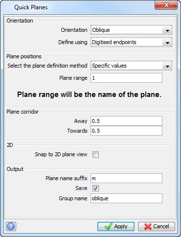
- First, create the oblique plane that all your subsequent parallel planes will be based off.
Use Planes > Quick planes to access the form below. The plane corridor is the viewing corridor width either side of the plane. As you will be creating 1m wide parallel planes in this example, a corridor of 0.5 away and toward will enable you to cycle through the planes and view the entire object.
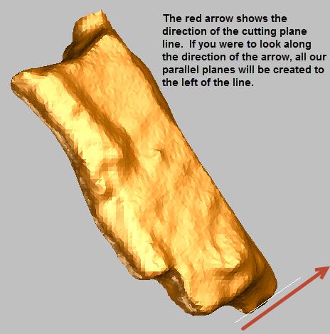
- When the form is applied, Surpac will ask you to “click and drag to define the cutting plane”. It is important to drag the line in the correct manner, as our parallel planes will be created to the left of the line that is dragged.
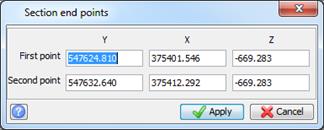
- Once the cutting plane line is defined, a confirmation dialog box appears, giving you an opportunity to modify the coordinates of the axis line.
- The data will be shown with the view now honoring the plane definition.
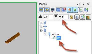
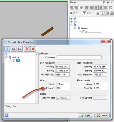
- Note that there is a sequence number associated to every plane. The sequence number determines how your planes will be cycled if you use the F11 and F12 keys or the forward and backward icons. In other words, it is not the plane name (in this case 1m) that determines the sequence but the sequence number.
Right clicking on the 1m plane and choosing “Properties” will enable you to see that the default sequence number is 100 (see below image). We need to keep this in mind when creating parallel planes.
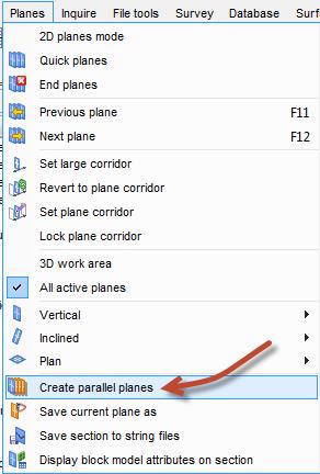
- Now, we are going to create parallel planes (Planes > Create Parallel Planes)
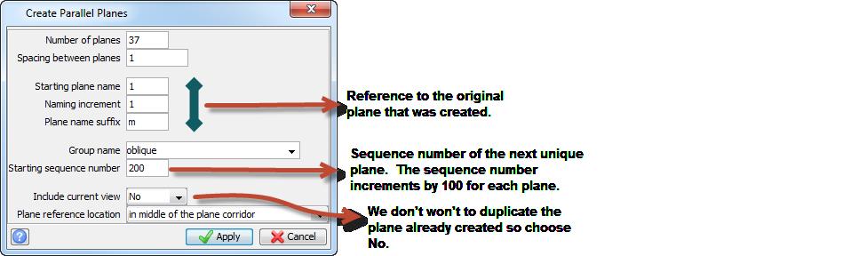
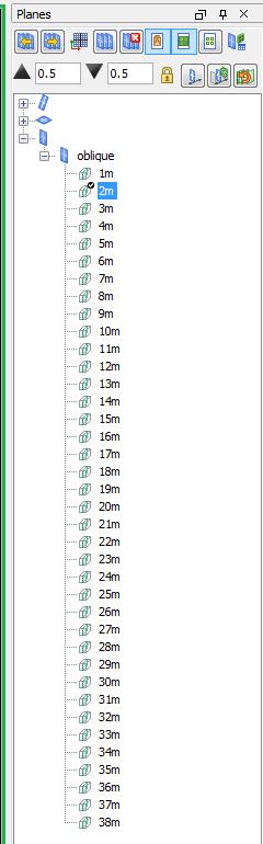
- The object we are creating planes for is roughly 38m long (Distance measured along a 325° bearing) therefore we will create 37 more planes to go with the original oblique plane at 1m increments.
- All the parallel planes are now created. If you select their properties, the sequence numbering should go from 100 to 3800 at an interval of 100. You can then use F12 to cycle forwards through the planes or F11 to cycle backwards.
In the next blog post, I will demonstrate how to create a string file for any object displayed in graphics that a plane passes through. I’ll be able to turn this into a macro so you can save all your section strings at the press of a button – look out for it next week!
For other posts in the Planes series, view: