The engineering of propellers determines the performance and hydrodynamic efficiency of ships, submarines and other vessels. Engineers not only need to understand the thrust and drag produced by the propeller, but also effects such as cavitation and wake noise. Conventionally, this can only be measured after constructing prototypes for water tunnel testing and sea trials. Optimizing performance and resolving problems requires multiple prototype iterations, resulting in increased costs and longer development times. Simulation offers an alternative, allowing engineers to analyze and optimize performance on a virtual twin of the real propeller without a physical prototype.
Why Simulate Propellers?
The propeller is the crucial component that transfers power from the engine into the water. Even small optimizations can have a huge impact on the performance of the entire vessel and the efficiency with which it converts fuel energy into thrust.
The propeller has to withstand massive forces as it pushes thousands of tons of ship through the water, often against significant waves. The propeller must be robust enough to withstand these forces, and in particular, it must be able to withstand the damage caused by cavitation, as the rapid motion of the blades causes bubbles which collapse and produce powerful shockwaves.
Propellers also produce extremely high noise levels – the largest ships can produce noise levels of 200 dB in water, with the propeller as the main noise source – which not only affects the detectability of vessels, but also causes noise pollution and injures or kills sea life.
Tackling propeller engineering challenges requires designers to be able to analyze and understand their designs. Traditionally, this is done using physical prototypes in a water tunnel or fitted to a vessel. Constructing a physical prototype costs time and money, and each design iteration requires a new prototype.
Simulation allows engineers to analyze the performance of a design before constructing a physical prototype. This allows faster design iterations, reduces prototyping and accelerates the design process. If issues are identified, design changes can be investigated and geometry optimized.
SIMULIA PowerFLOW is well-suited for the challenges of propeller simulation. It uses the Lattice Boltzmann Method (LBM), a powerful simulation technique that can handle complex geometry – for example, a detailed propeller mounted on a whole vessel – and realistic turbulence. PowerFLOW uses a fully compressible, inherently transient solver, meaning there is no requirement for additional “acoustic models”, or extra 3rd party tools. The physics models are universal and have been validated extensively for a wide range of industrial applications. PowerFLOW is available on both CPU and GPU, allowing flexibility regarding the chosen hardware.
Given the distinct characteristics of the near and far wake regions, it is more efficient to split the problem into two simulations. This approach enables the use of the most suitable simulation methods for each region. The novel transient boundary seeding technique implemented in PowerFLOW can efficiently divide the simulation domain, reducing the overall computation time without compromising accuracy. This can allow the simulation of very large domains, which is useful for tracking the wake downstream.
Propeller Simulation
To demonstrate propeller simulation with PowerFLOW, we will use the INSEAN E1619 propeller, a seven-bladed generic submarine propeller, developed by INSEAN. Its hydrodynamic performance as well as wake behavior was experimentally analyzed using a force balance system and laser Doppler velocimetry, respectively, during open water testing. The table below provides the principal parameters of the propeller.
| Parameters | Values |
| Number of Blades, Z [-] | 7 |
| Propeller diameter, DP [m] | 0.485 |
| Propeller pitch ratio, P/DP at 0.7RP [-] | 1.15 |
| Expanded area ratio, AE/AO [-] | 0.608 |
| Hub diameter ratio, d/DP [-] | 0.226 |

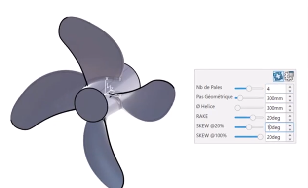
The first step is to model the propeller. For this, we used CATIA on the 3DEXPERIENCE platform. CATIA is widely used in industry to design and model complex products and systems, and it is integrated with SIMULIA products through unified modeling and simulation (MODSIM). With MODSIM, the design geometry can be converted directly into a simulation model, maintaining traceability and associativity between the model and simulation. This ensures that any design changes are automatically reflected in the model, and features in the simulation results can be traced back to the original design.
In PowerFLOW, the simulation is set up to replicate realistic water tank testing as closely as possible. This includes accurately modeling the water tank’s geometry and dimensions, the inflow velocity and pressure conditions, wall boundary conditions, as well as a hydrostatic pressure outlet condition. The propeller is simulated using a moving mesh approach within a Local Rotating Frame (LRF), enabling the physical rotation of the actual geometry within an axisymmetric domain. This allows the accurate capture of unsteady interactions between the blades and the surrounding flow, as well realistic wake propagation. Operating conditions are varied, with inflow velocities ranging from 3 m/s to 9.25 m/s. Results are averaged over 2 rotations. The simulation time for this workflow is comparable to an unsteady RANS simulation, while maintaining the same accuracy for performance parameters.
Validation Against Measurement
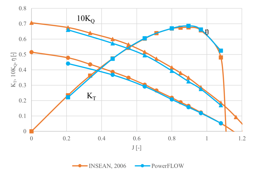
Figure 2 illustrates the performance metrics of the propeller, including thrust (KT), torque (10KQ), and efficiency (ŋ), comparing the numerical results with experimental data. The simulated results agree closely with the measurements, with a maximum error of just 8%. The results are particularly good for higher advance ratios, demonstrating the effectiveness of the LBM technique for high Mach number flows. Measurement data is from the Propeller Model INSEAN E1619, INSEAN test: March 16th. 2006 by Andrea Mancini, owned by CNR-INSEAN.
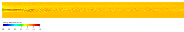
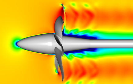
Below is a visual representation of the axial velocity field around the propeller, captured as an instantaneous snapshot from the PowerFLOW simulation. This detailed visualization illustrates the complex flow structures generated by the propeller blades, emphasizing the need for a simulation method like LBM that can accurately and efficiently model turbulent flow and complex geometry.
Moving to a Fully Integrated MODSIM Process, From Modeling to Manufacturing
The design does not end here. There are several other aspects that can be considered by the engineer. Thanks to the MODSIM process, all simulation technology is available in a single workflow, and the propeller can be integrated with different parts of the design, such as the hull and transmission, to allow further analysis. Considerations include:
Noise
The propeller is responsible for the majority of noise produced by most vessels. Propeller noise has always been an important consideration where detectability and passive sonar are concerns, but now there is also increasing pressure to protect wildlife. The noise produced by ships travels for miles in the water, and can not only distress wildlife but even kill it. One potential next step would be to conduct an acoustic analysis to model and mitigate noise pollution caused by a propeller’s cavitation or near wake fluctuations.
Installed Performance

A propeller does not exist in isolation – it is a part of a major larger vessel. The propeller needs to operate efficiently while in the wake of the vessel’s hull. The MODSIM workflow helps calculate the performance of a propeller under real sea conditions, not just in test environments. The simulation can include the entire vessel and its wake, aiding in determining the so-called self-propulsion points, where the vessel’s drag equals the propeller’s forward thrust.
Manufacturability
A design is useless unless it can be manufactured. Engineers need to ensure that the manufacturing process does not introduce weak points into the propeller, which could lead to premature failure. Simulation can model the manufacturing process and the manufactured propeller. A particular area of interest is additive manufacturing (“3D printing”), which can enable new propeller designs to be realized, but requires careful analysis of the manufacturing process. See our recent blog post to learn more about simulating the additive manufacturing of marine propellers.
Conclusion
Simulation allows marine engineers to design quieter and more efficient propellers. PowerFLOW is well-suited to the challenges of propeller simulation, using the Lattice Boltzmann Method to accurately and efficiently model fluid flow around the propeller. The accuracy of PowerFLOW has been verified against established benchmarks, showing close agreement with the measurements. Simulation can be incorporated in the design workflow using a unified modeling and simulation (MODSIM) approach. SIMULIA PowerFLOW integrates with design tools such as CATIA and other SIMULIA simulation tools on the 3DEXPERIENCE platform.

Interested in the latest in simulation? Looking for advice and best practices? Want to discuss simulation with fellow users and Dassault Systèmes experts? The SIMULIA Community is the place to find the latest resources for SIMULIA software and to collaborate with other users. The key that unlocks the door of innovative thinking and knowledge building, the SIMULIA Community provides you with the tools you need to expand your knowledge, whenever and wherever.
 Stephen Jorgenson-Murray
Stephen is an Advocacy Offer Marketing Specialist in Global Marketing.
 Wouter Van Der Velden
Wouter holds a PhD in aerospace engineering and has been working on modeling and simulation topics for over 10 years at Dassault Systemes. He is an senior industry expert and responsible currently for the simulation portfolio and go-to-market material and strategy for the marine and offshore industry.