Whenever I come in to land, I am always conscious of the importance of the airplane’s landing gear, which needs to absorb the weight of the airplane and its passengers while transitioning from flight to rolling on the runway. The design of the landing gear is further complicated by the need to minimize weight while maintaining compactness when stowed within the landing gear bay. In this blog post, we examine how design and simulation teams collaborate during the development of the landing gear to ensure that the defined criteria are met during the design iteration process.
Aircraft Landing Gear System
Within many companies, the design and testing departments are separate and rely on manual data transfer between them. The designers will continually update their designs to reflect changing requirements, while the testing department may conduct analyses using outdated design data. The transfer of the latest design to the testing department is often a manual process that requires converting the input data for the simulation tools. This process is time-consuming and subject to human error. Likewise, after the simulation is complete, any feedback to the design department is manually completed and separated from versioning in the resulting design updates.
To alleviate the issues associated with the design and simulation departments working independently, by bringing both departments to use the 3DEXPERIENCE platform results in a single source of truth and reduces the need for manual data updates in simulation tools after a design update. This unification of modeling and simulation is what we refer to as MODSIM (MODeling and SIMulation).

Improving an Aircraft’s Landing Gear with MODSIM
Let’s examine how this is achieved with an example: a landing gear system, which is crucial for ensuring aircraft safety during repeated landings, takeoffs, and taxiing. In addition to being robust and durable to withstand harsh landings, a landing gear system must be compact and lightweight to minimize its impact on an airplane’s fuel efficiency. It is also important that the landing gear does not destabilize the plane during the critical climbing and descent maneuvers.
At various stages of the landing gear’s development, designers must evaluate several key aspects of their design. For instance, do the components of the landing gear assembly move appropriately relative to one another, i.e., is the mechanism’s kinematics accurate? Is there a clash or interference between any of the components? Does the landing gear assembly fit in the aircraft bay and still accommodate hoses and cable routing? How do any modifications to the design impact the functioning of the landing gear system? All these questions, along with several more, can be answered by our easy-to-use yet powerful motion simulation technology on the 3DEXPERIENCE platform. The details of the motion roles available on the platform are discussed in detail in this blog.
Airplane Landing Gear Mechanisms
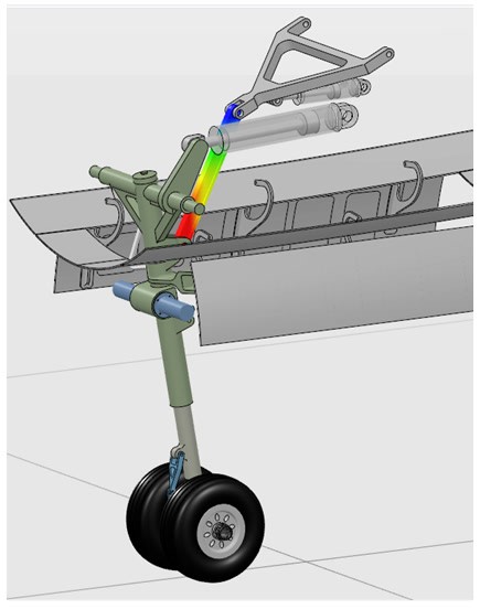
A typical workflow involves the designer creating parts for the various components of the landing gear and defining the connections/constraints (named engineering connections in the 3DEXPERIENCE platform) between them to establish the assembly kinematics. They can then simply launch one of the motion apps to automatically generate a motion mechanism and simulation model that contains the bodies and joints representing the different components and their connections, respectively.
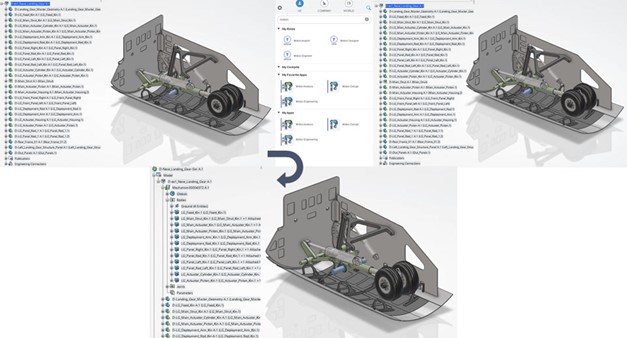
This ability to set up a motion mechanism/simulation in an automated manner (with just a few clicks) represents a significant departure from the traditional method of exporting CAD/geometry/design data into a simulation environment, and then building a simulation model that lacks associativity with the design.
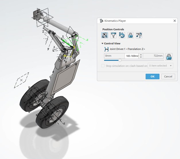
Once the motion simulation model is set up, designers have powerful/advanced motion-specific features at their disposal. Using an easy-to-use online kinematics player, the designer can validate the kinematics of the landing gear mechanism by adjusting joint positions with sliders, ensuring it retracts/extends correctly, and/or that the lock strut is in the correct position.
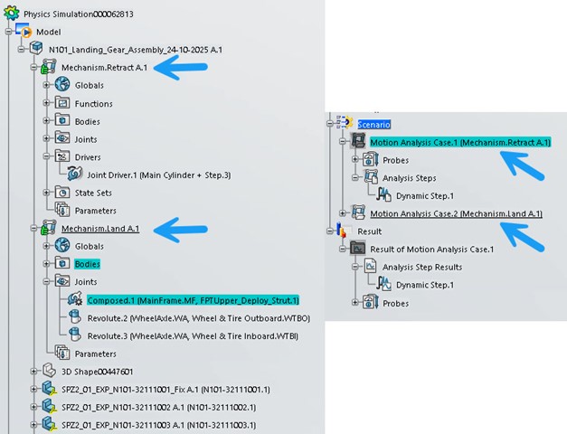
The motion apps allow the motion analyst to define several mechanisms, so that in the same model, they might have a driven mechanism representing the retraction of the landing gear, while a second mechanism may provide the movement required for a taxiing maneuver. Additionally, based on the defined mechanism, several scenarios can be defined and rerun after any design updates.
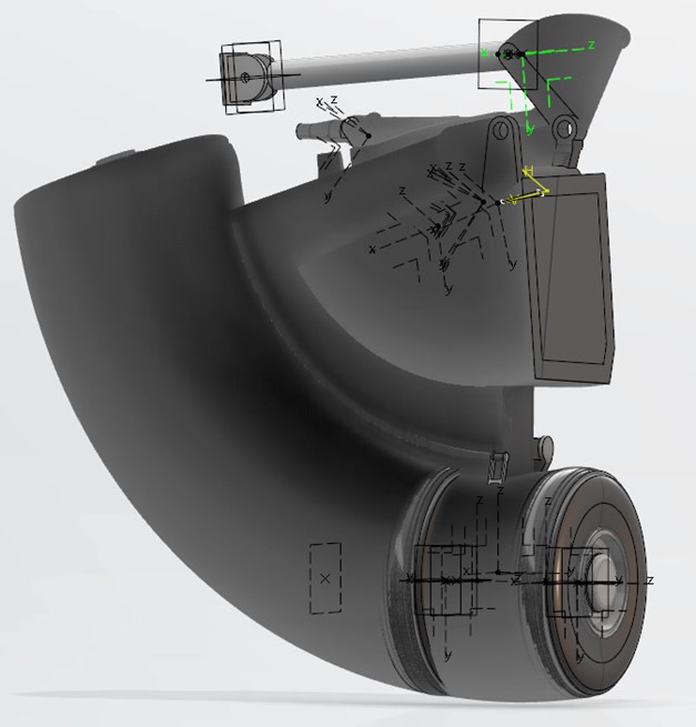
Designers can also use advanced motion-specific probes to determine the minimum distance between components or check for clash/interference between them.
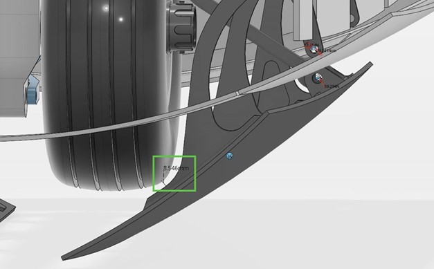
The designer can easily generate and visualize the swept volumes of individual or multiple components. The generated sweep volume can be accessed on the platform by the design team responsible for the bay and cable routing, so they can clearly see the space occupied through its full range of motion.
These features can guide critical design decisions, such as
- The necessary clearance between components — the gap between the landing gear wheel and the bay door.
- The space constraints for cable/hose routing in the aircraft bay can be determined by the total volume occupied by the landing gear mechanism during its full range of motion.
Now, if the output from the minimum distance or swept volume analysis does not meet the requirements, the designer can update the geometry/design and assess the impact on the minimum distance/swept volume outputs. The best part is that this design update is seamlessly transferred to the motion simulation model without any user intervention. As such, our unified modeling and simulation (MODSIM) environment ensures associativity between the geometry and simulation models, enabling quick assessment of the design against multiple KPIs.
Combining the Environments of Landing Gear Modeling and Simulation Processes
And here’s the kicker: a motion simulation engineer/analyst can collaborate with the designer in the same environment and access the same data set to perform more advanced simulations. They can simply build on the simulation model created by the designer to include advanced bushing representations or flexible components, thereby increasing fidelity and enabling a more detailed analysis.
The benefit of a common model is that it avoids the situation I have found myself in the past: attending a meeting to present the findings of my simulation analysis, only to discover that I have been using out-of-date data.
Additionally, the MODSIM environment allows democratization of the engineering process. For instance, if the designer identifies a potential change that improves the packaging of the landing gear system in the aircraft bay, they can be empowered with a templatized detail simulation model to quickly assess if their design change can affect the dynamics of the landing gear mechanism.
3DEXPERIENCE Collaboration for CATIA and SIMULIA Technologies
What’s more, the 3DEXPERIENCE offers a level of collaboration that goes well beyond that between a designer and a simulation expert. Other stakeholders, such as the system architect and program/portfolio manager, can be informed about the various stages of design, analysis, and development. As the project progresses, new versions of files are created, and the changes need to be propagated through the entire team to ensure that everyone is working with the latest data.
As seen in this blog post, the MODSIM approach integrates complete CATIA and SIMULIA technologies together on the 3DEXPERIENCE platform to provide a common user interface and data model for modeling and simulation.
MODSIM comes with various benefits, such as:
- Increase Design Confidence:
By embedding simulation into the design process, engineers can accurately predict the kinematic behavior of landing gear. Automating the design exploration space with multiple iterations reduces uncertainty. - Reduce Costs:
MODSIM shifts costs to an earlier product development phase, helping to lower the overall cost by avoiding late-stage failures. - Reduce Time:
Reuse models, physical test data and accrued knowledge to accelerate and streamline the development process. - Powerful Collaboration:
Real-time collaboration enables team members across the globe to leverage each other’s knowledge and expertise, thereby realizing solutions more rapidly and reducing rework. - Single-Source Data:
Landing gear designers and analysts work on the same model, thus avoiding translation and version control issues between CAD and CAE.
Our 3DEXPERIENCE platform provides a robust solution that enables the storage of all project data in a single, unified source of truth.

Interested in the latest in simulation? Looking for advice and best practices? Want to discuss simulation with fellow users and Dassault Systèmes experts? The SIMULIA Community is the place to find the latest resources for SIMULIA software and to collaborate with other users. The key that unlocks the door of innovative thinking and knowledge building, the SIMULIA Community provides you with the tools you need to expand your knowledge, whenever and wherever.

Tom Burton is a SIMULIA Industry Process Senior Consultant. After Tom graduated from University of Birmingham, school of manufacturing and mechanical engineering, in 1999 he started his career as a Simpack sales and support engineer in the UK. During 2000, he visited Simpack HQ and has remained in Germany every since. He undertook many customer projects in software customization, and as the company grow he became part of the development team. After the acquisition of Simpack by Dassault Systemes in 2014, he setup the newly formed back-end support team and integrated many 3DS workflows with Simpack development tools. In 2021 he took up his current position as an Industry Process Senior Consultant, where his Simpack knowledge is used to maximize the value our customers derive from our solutions