Summary
The vehicle market is evolving rapidly. New players are entering the market, the drive for vehicle electrification is ongoing, many variants of a vehicle are investigated prior to freezing the design, and sustainability is a major topic. In this context, vehicle aerodynamics is ever more crucial. It directly impacts the vehicle range and plays a major role in meeting regulation targets. Vehicle manufacturers must also keep in mind the need for a shorter time-to-market, where one must design faster and not permit late-stage redesign. This all means that a faster assessment of vehicle aerodynamics is imperative. In the past and present, computational fluid dynamics (CFD) has opened the door to virtual aerodynamic testing, allowing manufacturers to test their vehicle shapes before developing a costly and time-intensive prototype that then needs to be experimented on using a wind tunnel. While high-fidelity CFD, such as the PowerFLOW software offered by Dassault Systèmes (3DS), will remain an integral part of the aerodynamic development process of major OEMs, the growth of machine learning (ML) and continual improvement of its algorithms has opened doors to speed-up computational aerodynamics. The current work illustrates how aerodynamic data obtained from the 3DS CFD PowerFLOW software combined with data-driven methods can enable car manufacturers to obtain clean 3D contour plots of the vehicle’s surface X-force distribution, the associated integrated vehicle drag force and more within several minutes on a single GPU (after training of the ML model). This represents a significant reduction in computational cost and time, as running a high-fidelity aerodynamics CFD simulation requires several hundred CPUs and a couple of hours. More importantly, the error between the ML predicted drag force and the true PowerFLOW value is not larger than 3%. The geometry investigated is the open-source DrivAer car model with varying wheel spoke number and width.
Introduction
The use of the term digital twin is becoming more and more widespread. It represents a concept in which a digital replica of an object, or even a living being, is created to better understand, engineer, and optimize the real-life twin. So far, in the realm of vehicle aerodynamics, low-fidelity and high-fidelity computational fluid dynamics (CFD) software has been used to predict and improve the aerodynamic behavior (e.g. drag, lift, and yaw characteristics) of the car, thereby bypassing the need for costly physical prototypes until the very final stages of the vehicle design cycle. However, a proper digital twin of a vehicle should be able to illustrate the effect of geometry changes in near real-time, which, so far, using conventional computing architectures is not possible. Quantum computing, a very nascent technology, may solve this, but, for now, the only option is to resort to fast surrogate machine learning (ML) models. These models have learned from past aerodynamic data to predict the new aerodynamic performance of vehicle shapes that were not seen during the ML model training phase. This prediction speed-up solves the global problem of an increasing need for a shorter time-to-market in an ever-more competitive market landscape, where there is a drive for vehicle electrification and there are stricter sustainability regulations as well (see figure 1).

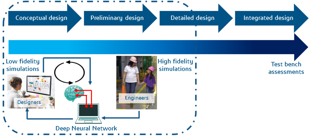
The idea is to embed the trained ML model(s) in the design stage such that the degree of fidelity that was previously only possible at the detailed design stage is now possible during the conceptual design phase as well, providing conceptual vehicle designers more aerodynamic insight into their proposed vehicle shapes and preventing late-stage design failures (see figure 2). Specifically, the goal of this work is to demonstrate that ML can be used as a surrogate model to reduce the use of CPUhrs intensive PowerFLOW CFD simulations for aerodynamic drag prediction, while significantly accelerating the compute time from several hours to merely several minutes.
Methodology
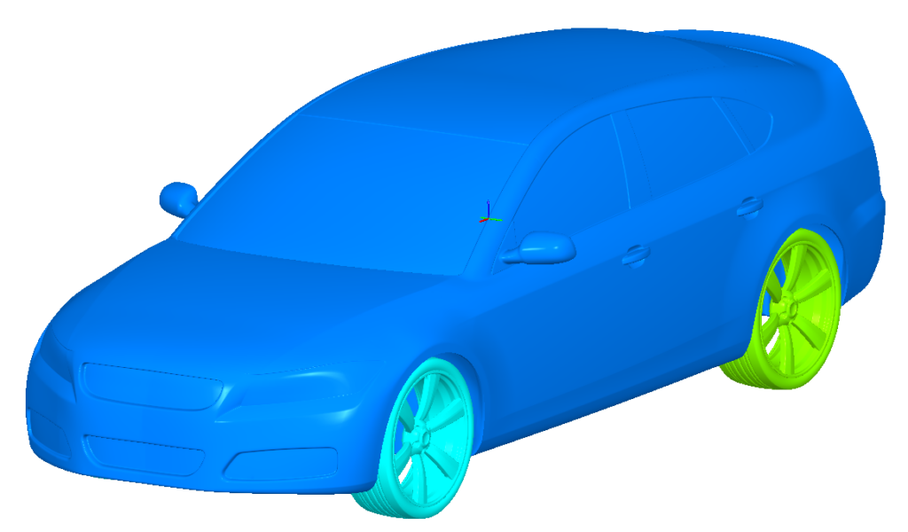
As a use-case, the following optimization study is analyzed: a design-of-experiment (DOE), where the tire spoke number and spoke width of the open-source DrivAer car geometry (see figure 3) are varied, with the optimization goal being the identification of the lowest vehicle drag configuration. In figure 4, the DOE design space is depicted. Red squares represent the simulation set that is used to train the ML models, green circles are the validation data points used in the ML training process to observe ML model convergence, and the blue triangles represent the blind test sets that will be used to see how well the ML models generalize to unseen vehicle geometries. The design space extremes are illustrated in figure 5.
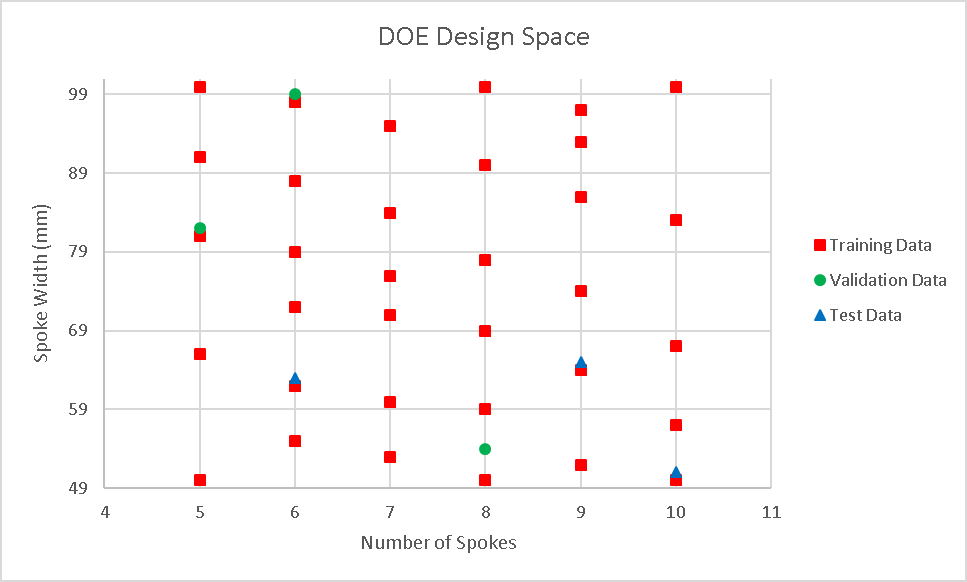
| Fig. 4: DOE design space |


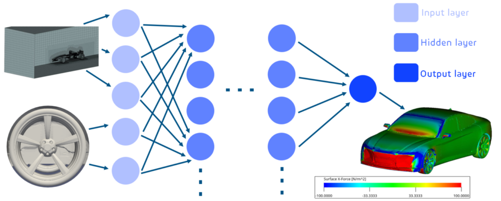
The study can be broken down into two segments: the CFD portion and the ML model part. During the CFD phase, 40 high-fidelity simulations are prepared in PowerDELTA, set-up in PowerCASE, run with PowerFLOW and some results are subsequently visualized in PowerVIZ as a sanity check that the data is reasonable. Each simulation takes about 6 hours and requires up to 300 CPU cores. Sample aerodynamic result visualizations are depicted in figure 6 for the Dassault Systèmes (3DS) E-car geometry. For this study, the critical surface field representation is the surface X-force distribution. Once the CFD data is collected, 34 simulation points are used to train deep learning neural network models that are written in Python with 3 simulation points used as validation points. A schematic of the feed-forward neural network models applied is depicted in figure 7 with the output data again represented by the 3DS E-car geometry. The input layer of the neural network models is fed with x-, y-, and z-coordinate data, as well as the spoke number and spoke width. This information is then propagated through the hidden layers of the neural network and, finally, at the output layer one obtains the surface X-force distribution of the vehicle. Training the neural network models takes approximately 3 days on a Windows workstation with a single GPU card. Meanwhile, the inference step, where the surface X-force distribution for vehicle geometries not seen during the neural network model training phase is predicted, merely takes several minutes.
Results
Before assessing the predictive capabilities of the trained ML models, it is imperative to check that the models are not under-fitting nor over-fitting the training data. This is done by looking at the mean-square-error (MSE) of the models as a function of training epoch. Two sample plots are provided in figure 8. Although for the 3DS E-car, similar orders of magnitude were achieved for the DrivAer car study presented in this article. Evidently, the MSE decreases almost monotonically and stays low as well, illustrating that the models should generalize well when exposed to unseen vehicle geometries. Furthermore, the MSE has an order of magnitude of O(10-3), which is reasonable as well.

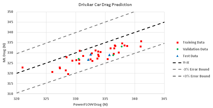
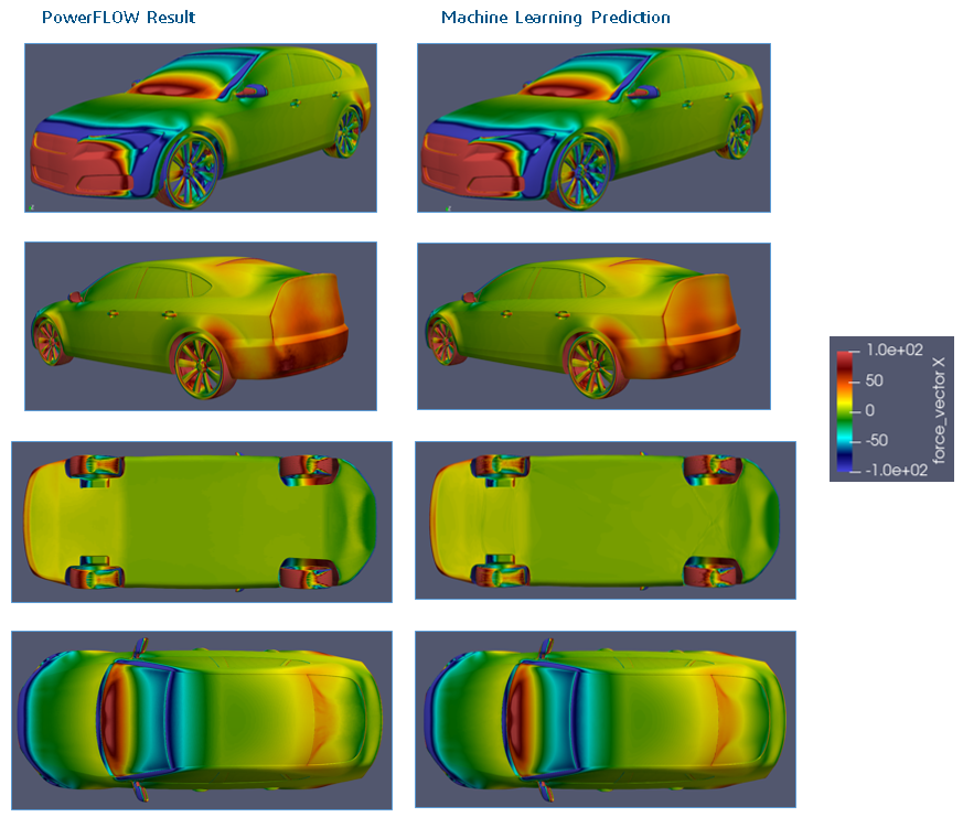
Now, one can look at the ML models predictive capabilities. For the blind test points, table 1 shows the drag force deltas between the true PowerFLOW results and the ML model outcomes and, more importantly, the percentage error. Evidently, the percentage error is around 2% for all three test cases, which is a very good outcome. Beyond that, the trained ML models were applied to all simulation points: training points, validation points, and test points. The associated accuracy of the predications is depicted in figure 9. Here, one can clearly see that the error lies within the 3% error bound. It is also interesting to note that there is a bias in the ML model results; the ML models consistently under-predict the integrated drag force. Having looked at the integrated drag force, surface X-force distribution plots provide further insight into the predictive capabilities of the ML models. Figure 10 shows these surface contour plots from different angles and viewpoints for run 37 (similar plots are obtained for all other runs). It is quite clear to see that there is almost no difference between the true PowerFLOW results and the ML predicted results. This substantiates the claim that the ML models are good surrogates for expensive high-fidelity PowerFLOW aerodynamic simulations.

Conclusion
Overall, a multi-model machine learning approach based on simple feed-forward artificial neural networks has been validated for the use of external aerodynamic drag force prediction of clay-model like vehicles. Once the ML model(s) have been trained on a single GPU for ~ 3 days, inferences (i.e. predictions) of drag force for unseen vehicle geometries take ~2 minutes as opposed to running a CPUhr intensive high-fidelity PowerFLOW simulation that takes ~6 hours on up to 300 CPU cores. Importantly, the percentage error between the true CFD PowerFLOW data and the ML model predictions of integrated drag force lies at less than 3%.
Future Work
A number of avenues for future work exist. One still needs to tune the ML model hyper-parameters to accelerate the ML model training and inference steps, while decreasing the ML model output error. It is also imperative that one extend the ML model predictive capabilities to allow good predictions of open-grill vehicle geometries with engine bay components. Furthermore, one also needs to build ML models to allow prediction of fluid volume velocity, thereby allowing the identification of separation lines around the vehicle. Finally, one could also envision the construction of generative AI models that create a new/optimized vehicle geometry with minimal separation lines and, therefore, close to zero low pressure drag enhancing wake regions.
Firoz Gandhi is a computational engineer with specialization in CFD. He completed his Master’s in computational modeling & simulation from TU Dresden and has experience working on several research projects touching various aspects of fluid dynamics such as turbulent flow, multi-phase flow, external and internal flows, etc. While working on his Master’s thesis, Firoz developed a custom algorithm to model the wall-slip effect for a non-Newtonian fluid and implemented it in OpenFOAM, achieving impressive accuracy. During his internship at Dassault Systemes, Firoz contributed to multiple projects, managing some independently while assisting colleagues on others. His passion for methodology development has recently led him to explore the integration of machine learning with CFD, a field he aims to build his career in.


Interested in the latest in simulation? Looking for advice and best practices? Want to discuss simulation with fellow users and Dassault Systèmes experts? The SIMULIA Community is the place to find the latest resources for SIMULIA software and to collaborate with other users. The key that unlocks the door of innovative thinking and knowledge building, the SIMULIA Community provides you with the tools you need to expand your knowledge, whenever and wherever.

