Challenge: Designing lightweight radomes that protect antennas without affecting performance. They developed a honeycomb structure that is strong and light, but needed a solution that would allow them to optimize this structure for best performance.
Solution: National Aerospace Laboratories use CST Studio Suite to optimize electromagnetic properties of radomes. Using CST Studio Suite, they can simulate the honeycomb structure at either the unit cell level or the entire radome structure and even the installed performance on a platform.
Benefits: NAL developed a radome with >90% transmission across the 33-36 GHz frequency band.
Who is National Aerospace Laboratories?
National Aerospace Laboratories (NAL) is a constituent of the Indian Council of Scientific and Industrial Research (CSIR). Founded in 1959, its mission is to focus on research and development for advanced aerospace technologies. It develops new aerospace technologies, builds small and medium-sized aircraft, and supports India’s national aerospace programs and industry.
One important area of aerospace technology is antenna systems. Antennas mounted on aircraft and ground stations are used to transmit and receive radio and data signals for communication, and radar signals for navigation and ranging. A crucial part of any aerospace antenna system is the radome.
What is a Radome?
Radomes (short for radar domes) are covers that protect antennas from damage, weather and soiling, and improve the aerodynamics of the platform the antennas are installed on. They are widely used for applications including radar ground stations, communication towers, and antennas on aircraft. Radomes need to be transparent to radio waves in the frequency band of interest – regardless of incident angle and polarization – but also strong, lightweight and weatherproof.
The major electromagnetic challenge for radome design is ensuring the best possible transmission of signals through the structure. Whenever electromagnetic waves reach an interface between materials, some portion of the energy is reflected or absorbed rather than transmitted. The greater the mismatch in electromagnetic impedance between two materials, the greater the reflection. Ideally, the radome would have identical electromagnetic properties to the surrounding air at the relevant frequencies to ensure perfect transmission. Energy can also be lost in the material through dielectric loss – electromagnetic wave energy being converted to heat in the material.
Improving Transmission with Honeycomb Sandwich
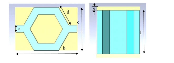
To design a high-performance radome, National Aerospace Laboratories (NAL) turned to honeycomb sandwich structure. This sweet-sounding material is a layered structure with thin outer layers and a filling layer between them in a honeycomb structure with empty space. The honeycomb is strong and lightweight, and because the outer skin layers are thin, the dielectric losses are small.
From an electromagnetic perspective, optimizing performance primarily means optimizing the thickness and geometry of the central honeycomb layer. Doing this with physical prototypes and testing alone is time-consuming and not always feasible due to limitations of available materials and the fact that results are not always transferable between different material thicknesses.
Optimizing Radome Performance with Simulation
To optimize their radome honeycomb structure for best performance, NAL turned to SIMULIA CST Studio Suite. This is an industry-leading electromagnetic simulation software with a wide range of solver technologies for electromagnetic problems across different frequencies and scales. A honeycomb structure can be simulated in CST Studio Suite at either the unit cell level or the entire radome structure, and even the installed performance on a platform.
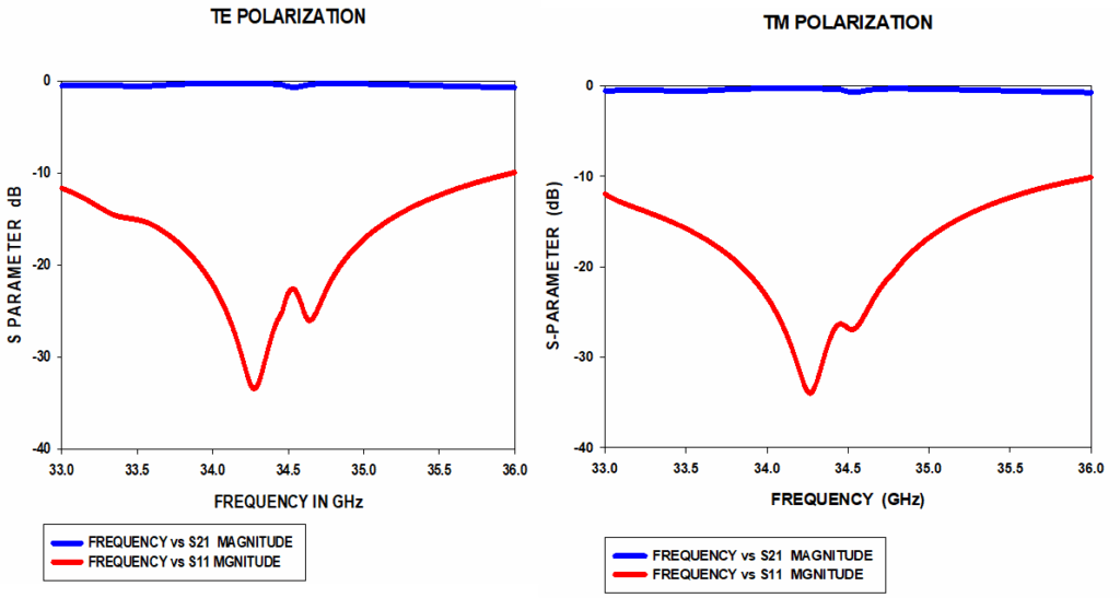
NAL used parametric optimization to quickly investigate how variations in thickness and geometry affect electromagnetic performance. In the example shown below, NAL wanted to develop a radome material for the 33-36 GHz radar band. This is a millimeter-wave frequency, meaning that dielectric losses in materials are expected to be relatively high; careful optimization is required to keep them at acceptable levels.
Simulation was able to model performance across the entire frequency band and at any polarization and angle. The researchers were not limited by the materials available to them for testing but could explore the entire design space to develop theories and find optimal designs. Simulation results match measured data closely enough to give NAL confidence in their theories.
With all CST Studio Suite solver technology in a single interface, NAL was also able to perform hybrid simulations, using multiple solvers to simulate complex antenna radome systems installed on platforms and thermal solvers to calculate how the radome heats up due to absorbed energy.
The final results are shown below. The radome design optimized in CST Studio Suite achieved a reflection coefficient (S11) below -10 dB across the frequency band of interest and a transmission coefficient (S12) close to 0 dB. Using simulation, NAL ensured that over 90% of energy was transmitted through the radome at all frequencies for all polarizations.

Interested in the latest in simulation? Looking for advice and best practices? Want to discuss simulation with fellow users and Dassault Systèmes experts? The SIMULIA Community is the place to find the latest resources for SIMULIA software and to collaborate with other users. The key that unlocks the door of innovative thinking and knowledge building, the SIMULIA Community provides you with the tools you need to expand your knowledge, whenever and wherever.

Katie is the Editor of the SIMULIA blog, an expert in engineering and scientific communication, and a strategic digital marketer. Katie has a BA in English and Writing from the University of Rhode Island and a MS in Technical Communication from Northeastern University. She is also a proud SIMULIA advocate, passionate about democratizing simulation for all audiences. Katie is a native Rhode Islander who lives just outside of her favorite city, Providence. She is a true New Englander and loves sharing all the cool things NE has to offer. She enjoys a variety of hobbies including history, astronomy, science/technology, science fiction, true crime, fashion and anything associated with nature and the outdoors. She is also mom to a 6-year old budding engineer and two crazy rescue pups.