
Background
Concrete is a complex but highly versatile material. Proper choice of the type and proportion of its constituents can enable it to have high compressive strength as well as resistance against environmental degradation. Available for centuries, concrete is the most widely used human-made construction material in the world. It is appealing because of its low cost, durability, and its ability to be formed into various shapes.
There is, however, one important challenge in designing with concrete: it is weak and cracks when in tension. In tensile regions, concrete needs reinforcement with other materials such as steel bars, cables, or meshes of fibers so the concrete carries the compressive loads and the reinforcement carries the tension. For proper design of reinforced concrete structures, one needs to identify, in detail, the regions that have the potential to be in tension and regions that remain in compression.
Abaqus can simulate the formation and propagation of cracking in concrete with and without reinforcement. Below we illustrate two representative cases: a reinforced concrete beam subjected to a uniformly distributed load, and a reinforced concrete slab subjected to a blast load.
Case 1: Reinforced Concrete Beam with Uniformly Distributed Load
Until about 200 years ago, unreinforced masonry (in arch or dome shapes) and timber beams were the main structural materials for spanning large spaces. The advent of steel and reinforced concrete in the mid-1800s provided engineers a better solution for large spans. These innovations drive construction to this day.
A beam’s main purpose is to span large spaces. Transverse loading on a beam gives rise to bending moments and shear forces together with the generation of compressive and tensile stress. In a reinforced concrete beam, the regions containing tensile stress can crack and such cracks can lead to structural collapse if not for the presence of reinforcement.
In this example, we subject a reinforced concrete beam of length 6.0 m and having a rectangular cross-section of 0.5 m x 0.3 m to a uniformly distributed load of 33 kN/m. The beam is a simply-supported beam with overhangs as shown in Figure 1. The supports are placed 0.5 m from the ends of the beam. The design of the beam, reinforcement configuration and loading conditions are for illustration purposes only.
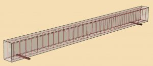
We represent the concrete behavior by the concrete damaged plasticity material model, and we define the reinforcement using the embedded element capability. The concrete damaged plasticity material model is available both in Abaqus/Standard, which is an implicit analysis code and in Abaqus/Explicit, which is an explicit dynamics analysis code. The reinforcing bars and stirrups are discretized using beam elements and these beam elements are embedded into the host elements modeled using solid elements.
The most common analysis use-case for structures in the construction industry is a static analysis case, wherein a load that is not changing with time is applied and the static response behavior of the structure is computed. This type of analysis can be done using Abaqus/Standard in most cases. However, when cracking and material damage is included in the simulation, implicit analyses can often have convergence problems and a limited state of the structure is difficult to obtain. Explicit dynamics, on the other hand, can be used for analyses in which a limit state needs to be reached. In such explicit dynamics analyses, the loading needs to be applied slowly to minimize any inertial effects.
In the reinforced beam examples presented below, the uniformly distributed load increases linearly from zero to a value of 33 kN/m over a time step. Abaqus/Standard is used in one example, and Abaqus/Explicit is used in the other, to simulate and predict the formation of cracks and deformations in the concrete as the beam is loaded.
The Abaqus/Standard analysis is run as a static analysis case. Abaqus/Standard provides a way to include viscoplastic regularization of the constitutive equations to improve the convergence rate in the softening regime. For this analysis, a viscosity value of 0.0001 is used.
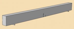
The static analysis shows that the cracking in concrete starts at a load value of about 25.08 kN/m. The DAMAGE output variable for concrete shows values greater than zero starting from this load value. The cracks extend as the applied load increases; however, simultaneously, as damage increases and the material degrades in stiffness, the time increment size used by the analysis reduces. The analysis progresses slowly until the maximum number of increments are reached, which occurs at the applied load value of 25.48 kN/m. The crack pattern at this load value is shown in Figure 2.
The use of a higher viscosity value can allow the Abaqus/Standard analysis to progress further; however, there can be implications in the accuracy of the results. Additionally, a higher value of viscosity can smear the effect of the cracks over larger widths.
In contrast to an analysis using Abaqus/Standard, which is an implicit analysis code, Abaqus/Explicit allows the analysis to progress further and can simulate the formation of an extensive pattern of cracks. Moreover, viscoplastic regularization is not required for the concrete damaged plasticity model in Abaqus/Explicit.
The Abaqus input files for the examples shown here are available in the SIMULIA Community.
For the analysis using Abaqus/Explicit, however, the load needs to be applied slowly over an extended time interval, to minimize the development of inertial forces. For the beam analysis, the load is applied linearly increasing from zero to 33 kN/m over a time interval of 1.0 seconds.
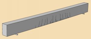
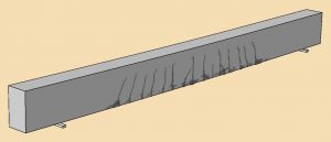
The predicted crack pattern in the concrete at an intermediate load value of 26.4 kN/m is shown in Figure 3. Figure 4 shows the crack pattern at the end of the analysis at the full load of 33 kN/m.
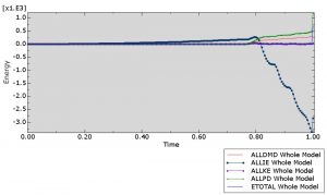
To ensure that the Abaqus/Explicit analysis replicates a quasi-static behavior, we compare the loading time to the natural period of vibration of the beam. The time period of the vibration mode of the beam corresponding to the expected deformed shape is about 0.05 seconds. To ensure a quasi-static analysis, the load application time used for this analysis has been chosen to be about 20 times the natural time period of the beam. Figure 5 shows the computed energy plots after the Abaqus/Explicit analysis, and these confirm that a quasi-static solution has been obtained. The kinetic energy remains small compared to the internal energy, damage dissipation energy, and plastic dissipation energy.
The beam used in the example shown here is just a simple structure; however, similar analyses can be done on complex structures to help identify cracking patterns that can then guide the placement of reinforcement.
Reinforced concrete beams can also be modeled using 1D beam elements. There will be savings on computational effort for large structures; however, the fidelity of the analysis will be compromised by the 1D approximation. Although the overall behavior of large frame structures can be approximately obtained using 1D elements, for detailed analyses at reinforced connections such as between beams and columns, a 3D representation would be more accurate.
Case 2: Reinforced Concrete Slab Subjected to Blast Loading
Building structures typically need to withstand conventional loads such as dead loads (like gravity) and live loads (such as wind or snow) as suggested in building design codes and recommended practices. However, in extraordinary situations, structures can undergo unusual loadings such as those from explosions or blasts. In some cases, the structure itself needs to be designed to act as a protective barrier to resist blast loads. In these instances, it is important to predict the way the structure may fail, break apart, or collapse. In the example below, we subject a reinforced concrete slab to a blast load and simulate its cracking and deformation behavior.
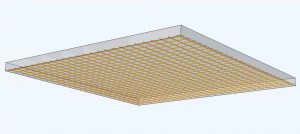
The reinforced concrete slab is placed horizontally. It is fixed on its edges and is subjected to a blast load from below. The slab has dimensions of 5 m x 5 m and a thickness of 0.2 m. Figure 6 shows a schematic of the slab. The blast load originates at a point located 2.5 m below the center of the bottom surface of the slab. The reinforcement configuration and loading conditions in this example are for illustration purposes only.
Abaqus/Explicit is used to predict the deformation and collapse of the slab due to the blast. The concrete damaged plasticity material model in Abaqus is used for this analysis, and reinforcement is defined using embedded element constraints. The slab undergoes severe deformation due to the blast, and several concrete elements in the slab get damaged and fail. The failed elements are automatically removed during the analysis by using the concrete failure option in Abaqus.
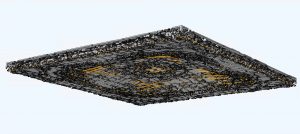
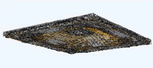
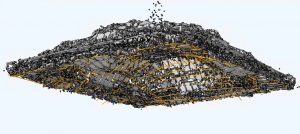
Figure 7 shows the deformed and cracked slab at 0.0125 seconds. Figures 8 and 9 show the cracked slab at 0.025 seconds and 0.05 seconds, respectively. The exposed reinforcing bars can be seen.
In this example, we have modeled the slab as a reinforced 3D solid structure with multiple solid elements through the thickness, and each element is allowed to undergo damage and can get removed individually. It is also possible to model this slab as a reinforced 2D structure using shell elements. Although the latter would save on computational costs, it would sacrifice the fidelity of the analysis, especially in the behavior of the slab through the slab thickness.
The SIMULIA documentation provides details on how to set up these kinds of models and how to specify concrete damaged plasticity, embedded element constraints, blast loading, and concrete failure.
For more information including the downloadable paper and the Abaqus input files, please visit the SIMULIA Community.

SIMULIA offers an advanced simulation product portfolio, including Abaqus, Isight, fe-safe, Tosca, Simpoe-Mold, SIMPACK, CST Studio Suite, XFlow, PowerFLOW, and more. The SIMULIA Community is the place to find the latest resources for SIMULIA software and to collaborate with other users. The key that unlocks the door of innovative thinking and knowledge building, the SIMULIA Community provides you with the tools you need to expand your knowledge, whenever and wherever.
Concrete structures need to be reinforced in regions subject to tension, to avoid cracking and structural failure. This blog post illustrates how structural simulation can identify regions of tensile stress within concrete structures, and predict the formation and propagation of cracks, both under uniform loads and blast loading.
Background
Concrete is a complex but highly versatile material. Proper choice of the type and proportion of its constituents can enable it to have high compressive strength as well as resistance against environmental degradation. Available for centuries, concrete is the most widely used human-made construction material in the world. It is appealing because of its low cost, durability, and its ability to be formed into various shapes.
There is, however, one important challenge in designing with concrete: it is weak and cracks when in tension. In tensile regions, concrete needs reinforcement with other materials such as steel bars, cables, or meshes of fibers so the concrete carries the compressive loads and the reinforcement carries the tension. For proper design of reinforced concrete structures, one needs to identify, in detail, the regions that have the potential to be in tension and regions that remain in compression.
Abaqus can simulate the formation and propagation of cracking in concrete with and without reinforcement. Below we illustrate two representative cases: a reinforced concrete beam subjected to a uniformly distributed load, and a reinforced concrete slab subjected to a blast load.
Case 1: Reinforced Concrete Beam with Uniformly Distributed Load
Until about 200 years ago, unreinforced masonry (in arch or dome shapes) and timber beams were the main structural materials for spanning large spaces. The advent of steel and reinforced concrete in the mid-1800s provided engineers a better solution for large spans. These innovations drive construction to this day.
A beam’s main purpose is to span large spaces. Transverse loading on a beam gives rise to bending moments and shear forces together with the generation of compressive and tensile stress. In a reinforced concrete beam, the regions containing tensile stress can crack and such cracks can lead to structural collapse if not for the presence of reinforcement.
In this example, we subject a reinforced concrete beam of length 6.0 m and having a rectangular cross-section of 0.5 m x 0.3 m to a uniformly distributed load of 33 kN/m. The beam is a simply-supported beam with overhangs as shown in Figure 1. The supports are placed 0.5 m from the ends of the beam. The design of the beam, reinforcement configuration and loading conditions are for illustration purposes only.
We represent the concrete behavior by the concrete damaged plasticity material model, and we define the reinforcement using the embedded element capability. The concrete damaged plasticity material model is available both in Abaqus/Standard, which is an implicit analysis code and in Abaqus/Explicit, which is an explicit dynamics analysis code. The reinforcing bars and stirrups are discretized using beam elements and these beam elements are embedded into the host elements modeled using solid elements.
The most common analysis use-case for structures in the construction industry is a static analysis case, wherein a load that is not changing with time is applied and the static response behavior of the structure is computed. This type of analysis can be done using Abaqus/Standard in most cases. However, when cracking and material damage is included in the simulation, implicit analyses can often have convergence problems and a limited state of the structure is difficult to obtain. Explicit dynamics, on the other hand, can be used for analyses in which a limit state needs to be reached. In such explicit dynamics analyses, the loading needs to be applied slowly to minimize any inertial effects.
In the reinforced beam examples presented below, the uniformly distributed load increases linearly from zero to a value of 33 kN/m over a time step. Abaqus/Standard is used in one example, and Abaqus/Explicit is used in the other, to simulate and predict the formation of cracks and deformations in the concrete as the beam is loaded.
The Abaqus/Standard analysis is run as a static analysis case. Abaqus/Standard provides a way to include viscoplastic regularization of the constitutive equations to improve the convergence rate in the softening regime. For this analysis, a viscosity value of 0.0001 is used.
The static analysis shows that the cracking in concrete starts at a load value of about 25.08 kN/m. The DAMAGE output variable for concrete shows values greater than zero starting from this load value. The cracks extend as the applied load increases; however, simultaneously, as damage increases and the material degrades in stiffness, the time increment size used by the analysis reduces. The analysis progresses slowly until the maximum number of increments are reached, which occurs at the applied load value of 25.48 kN/m. The crack pattern at this load value is shown in Figure 2.
The use of a higher viscosity value can allow the Abaqus/Standard analysis to progress further; however, there can be implications in the accuracy of the results. Additionally, a higher value of viscosity can smear the effect of the cracks over larger widths.
In contrast to an analysis using Abaqus/Standard, which is an implicit analysis code, Abaqus/Explicit allows the analysis to progress further and can simulate the formation of an extensive pattern of cracks. Moreover, viscoplastic regularization is not required for the concrete damaged plasticity model in Abaqus/Explicit.
The Abaqus input files for the examples shown here are available in the SIMULIA Community.
For the analysis using Abaqus/Explicit, however, the load needs to be applied slowly over an extended time interval, to minimize the development of inertial forces. For the beam analysis, the load is applied linearly increasing from zero to 33 kN/m over a time interval of 1.0 seconds.
The predicted crack pattern in the concrete at an intermediate load value of 26.4 kN/m is shown in Figure 3. Figure 4 shows the crack pattern at the end of the analysis at the full load of 33 kN/m.
To ensure that the Abaqus/Explicit analysis replicates a quasi-static behavior, we compare the loading time to the natural period of vibration of the beam. The time period of the vibration mode of the beam corresponding to the expected deformed shape is about 0.05 seconds. To ensure a quasi-static analysis, the load application time used for this analysis has been chosen to be about 20 times the natural time period of the beam. Figure 5 shows the computed energy plots after the Abaqus/Explicit analysis, and these confirm that a quasi-static solution has been obtained. The kinetic energy remains small compared to the internal energy, damage dissipation energy, and plastic dissipation energy.
The beam used in the example shown here is just a simple structure; however, similar analyses can be done on complex structures to help identify cracking patterns that can then guide the placement of reinforcement.
Reinforced concrete beams can also be modeled using 1D beam elements. There will be savings on computational effort for large structures; however, the fidelity of the analysis will be compromised by the 1D approximation. Although the overall behavior of large frame structures can be approximately obtained using 1D elements, for detailed analyses at reinforced connections such as between beams and columns, a 3D representation would be more accurate.
Case 2: Reinforced Concrete Slab Subjected to Blast Loading
Building structures typically need to withstand conventional loads such as dead loads (like gravity) and live loads (such as wind or snow) as suggested in building design codes and recommended practices. However, in extraordinary situations, structures can undergo unusual loadings such as those from explosions or blasts. In some cases, the structure itself needs to be designed to act as a protective barrier to resist blast loads. In these instances, it is important to predict the way the structure may fail, break apart, or collapse. In the example below, we subject a reinforced concrete slab to a blast load and simulate its cracking and deformation behavior.
The reinforced concrete slab is placed horizontally. It is fixed on its edges and is subjected to a blast load from below. The slab has dimensions of 5 m x 5 m and a thickness of 0.2 m. Figure 6 shows a schematic of the slab. The blast load originates at a point located 2.5 m below the center of the bottom surface of the slab. The reinforcement configuration and loading conditions in this example are for illustration purposes only.
Abaqus/Explicit is used to predict the deformation and collapse of the slab due to the blast. The concrete damaged plasticity material model in Abaqus is used for this analysis, and reinforcement is defined using embedded element constraints. The slab undergoes severe deformation due to the blast, and several concrete elements in the slab get damaged and fail. The failed elements are automatically removed during the analysis by using the concrete failure option in Abaqus.
Figure 7 shows the deformed and cracked slab at 0.0125 seconds. Figures 8 and 9 show the cracked slab at 0.025 seconds and 0.05 seconds, respectively. The exposed reinforcing bars can be seen.
In this example, we have modeled the slab as a reinforced 3D solid structure with multiple solid elements through the thickness, and each element is allowed to undergo damage and can get removed individually. It is also possible to model this slab as a reinforced 2D structure using shell elements. Although the latter would save on computational costs, it would sacrifice the fidelity of the analysis, especially in the behavior of the slab through the slab thickness.
The SIMULIA documentation provides details on how to set up these kinds of models and how to specify concrete damaged plasticity, embedded element constraints, blast loading, and concrete failure.
For more information including the downloadable paper and the Abaqus input files, please visit the SIMULIA Community.
SIMULIA offers an advanced simulation product portfolio, including Abaqus, Isight, fe-safe, Tosca, Simpoe-Mold, SIMPACK, CST Studio Suite, XFlow, PowerFLOW, and more. The SIMULIA Community is the place to find the latest resources for SIMULIA software and to collaborate with other users. The key that unlocks the door of innovative thinking and knowledge building, the SIMULIA Community provides you with the tools you need to expand your knowledge, whenever and wherever.

Deepak Datye is a Sr. Consultant, Technical Solutions, at SIMULIA. He is based at the SIMULIA headquarters in Johnston, RI. Over the past several years he has been focusing on Abaqus applications for geomechanics, civil engineering, and oil and gas. Deepak has been with SIMULIA since 2001, and holds a PhD in Civil Engineering from Stanford University.