The advent of the electric vehicle market brings with it numerous challenges for battery system development. For one, there is a significant proliferation of battery and cooling design. This means there are many designs to choose from, but limited (prior) test data to understand which battery and cooling design to choose. Additionally, there is a high pressure to reduce development time (i.e. time-to-market) as well as the battery development cost. Furthermore, a holistic design approach is sought after, where the full vehicle thermal design is accounted for. More specifically, cooling/heating of both the battery and cabin must be considered as well as an efficient design is needed for extended battery range.
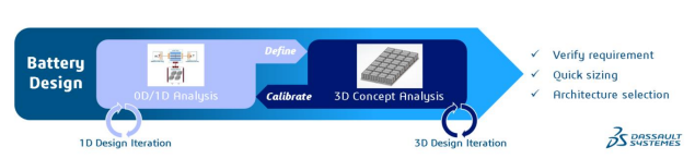
The objective of this blog post is to describe a fast, accurate and automated calibration workflow to accelerate battery conceptual design, component scaling, and performance trade-off analysis. This is achieved through an integrated 1D and 3D model correlation workflow for battery conceptual design. The user will not need to rely on past test data or correlation, can quickly evaluate and choose between designs, can perform drive cycle / full vehicle thermal system analysis, and can iterate and improve when more design detail is revealed. A pictorial representation of this process is illustrated in figure 1. First, a 3D simulation of the battery system is performed. The data is then used to calibrate a 0D/1D model, which enables an accelerated analysis of the battery system to be performed. One, therefore, has an ideal setting to iterate over many battery system designs in a short time, ultimately being able to then choose the optimal battery system and cooling design for the intended application. Subsequently, one returns to the higher fidelity 3D simulation world to validate the 0D/1D battery and cooling model, thereby closing the design loop illustrated in figure 1. The remainder of this blog post is organized into a methodology description that is subsequently followed by a description of a use-case and a concluding statement.
To begin, one starts with a battery cell level correlation. Specifically, one creates a 3D battery cell parametric model and characterizes / correlates a 1D battery cell parametric model from the Dymola Modelica library. This correlation work is then carried over to the battery module / pack level where, again, a 3D representation of the battery module and cold plate is used to characterize / correlate a 1D representation of the battery module and cold plate system from the Dymola Modelica library.
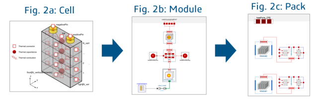
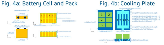
The Dymola Modelica library that is used to create the 0D/1D battery and cooling system representation offers a plethora of tunable parameters. At the battery cell level, one is able to discretize the thermal capacity, and parametrize thermal properties, either directly or calculated based on geometry and material data (see figure 2a). Meanwhile, on the battery module level, the individual cell behavior is maintained, but now thermal interactions between the cells and environment is accounted for as well (see figure 2b). At the battery pack level, one reuses battery module models and also considers additional housing and interfaces (see figure 2c). Moving on, the liquid cooling cold plate model (see figure 3) offers variable flow geometry with vectorized fluid channel for the independent modelling of parallel fluid channels and solid wall element discretization. It also enables a 2D wall dynamic thermal capacitance grid with 3D thermal inertia of the heat exchanger core to be accounted for. Overall, the parameterization of the cold plate correlates to the actual design data in terms of dimensions, material properties, and number of channels.
Having described the 0D/1D Dymola Modelica representation of the battery system and cooling pattern, the 3D model must now be described. The 3D representation of the battery system and cooling geometry is parametric (see figure 4a-4b). It has continuous parameters for the cell dimensions, housing, terminals, channel design and more. Meanwhile, discrete parameters account for the number of cells, modules and cold plate cooling channels. This parametric model is purposely made robust to implement it in an automatic workflow. Furthermore, for the computational fluid dynamics (CFD) and conjugate heat transfer (CHT) analysis, the 3DEXPERIENCE platform based FMK Reynolds-Averaged Navier-Stokes (RANS) solver is used. The solid domain is solved for using a finite element model (FEM). There is automatic contact detection for solid-to-solid contact and fluid-to-solid contact interfaces. Also, there is automatic fluid domain detection and sealing.
With both the 0D/1D and 3D battery system and cooling plate representations discussed, the subsequent step is to clarify the correlation methodology. Specifically, one wishes to correlate the 0D/1D model behavior with the 3D model as a reference. The strategy entails correlating the solid and fluid domains separately for better efficiency. Reason being, fluid convection behavior is non-linear (as made clear by the non-linear convection term in the Navier-Stokes equations), while solid conduction is linear in behavior (as made evident by the linear heat diffusion equation). For fluid convection, one therefore correlates flow dependent thermal convection behavior. With solid conduction, a two-step process is adopted: steady-state results are correlated by tuning the conduction path, while transient results are correlated by tuning the thermal mass distribution. The correlation workflow outlined above is automated. Dymola simulations and Python optimization routines are used for the parameter correlation. The optimization algorithm itself consists of the differential evolution method with a population of 10 and iterations up to 1000, where the final design is refined using the gradient method to minimize the prediction error with respect to the 3D result.
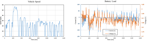
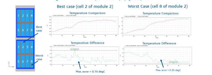
To illustrate the use of this 3D to 0D/1D correlation workflow for battery system development, validation is performed using an electric vehicle (EV) duty cycle where the lightweight vehicle battery load is taken from the United States Environmental Protection Agency (EPA) Urban Dynamometer Driving Schedule (UDDS) to represent typical city driving conditions. The associated vehicle speed and battery load is depicted in figure 5. For a battery pack consisting of two battery modules each with eight battery cells, the best and worst temperature comparison between the 3D and 0D/1D result is shown in figure 6. At best, the battery temperature delta is as low as 0.10°C, while in the worst case the battery temperature delta is as high as 0.26°C.
In summary, an integrated 0D/1D and 3D correlation workflow for EV battery system development has been presented. It has been shown that, even for a highly dynamic and realistic load cycle, good accuracy can be obtained when the 0D/1D model has been appropriately tuned based on the 3D battery system results. This means that for future battery system development work, the 0D/1D model can be used to provide high fidelity analysis even without a prior physical model. The presented workflow also represents a Dassualt Systèmes example of MODSIM, integrated modelling and simulation, and, thereby, is a proponent of Dassault Systemès’ long-term strategy of breaking silos between designers and simulation engineers while accelerating the product development cycle.

Interested in the latest in simulation? Looking for advice and best practices? Want to discuss simulation with fellow users and Dassault Systèmes experts? The SIMULIA Community is the place to find the latest resources for SIMULIA software and to collaborate with other users. The key that unlocks the door of innovative thinking and knowledge building, the SIMULIA Community provides you with the tools you need to expand your knowledge, whenever and wherever.

Dr. Faron Hesse graduated with a MEng in mechanical engineering from the Imperial College of London in 2016. During this degree, he worked for one year as an Aerodynamic Performance Engineer at the Red Bull Racing F1 team, winning the championship with Sebastian Vettel. Faron then pursued a sponsored MRes in fluid dynamics, again at the Imperial College of London. Finally, prior to starting to work for Dassault Systèmes in 2019 as an Industry Process Consultant in the T&M Supplier Fluids division, Faron completed a PhD in vehicle aerodynamics at the Imperial College of London.