Key Takeaways
- Computational fluid dynamics (CFD) lets white-goods manufacturers see how water and air move inside washing machines and tumble dryers before a physical prototype is built.
- In a multiphase simulation of a washing machine detergent dispenser fed with 0.01 kg/s of water at each of its three inlets, water first reached the outlet after about 2.65 seconds.
- In a transient simulation of a tumble dryer centrifugal fan running at 2,000 rpm, the fan moved about 0.22 kg/s of air and produced a pressure rise of about 92 Pa.
- The fan simulation showed strongly turbulent flow at the casing outlet, which makes that region the first candidate for geometric optimization.
- Both studies used the Fluid Dynamics Engineer (FMK) role on the Dassault Systèmes 3DEXPERIENCE® platform. Parametric design-of-experiment studies and AI surrogate models are the next steps.
Introduction
For many households, washing machines and tumble dryers are very familiar. These goods form a core part of a home’s furnishings and are used regularly. Despite their prevalence, it is very likely that most users do not think about the physics associated with such machines. It is taken for granted that they clean and subsequently dry clothes efficiently without damaging the fabric. This process does, however, entail precision engineering.
Why Does Fluid Dynamics Matter for Household Appliances?
At first glance, household appliances such as a washing machine and a tumble dryer are categorized as part of the Home & Lifestyle industry. Although they are also found in industrial contexts, such as hotels and hospitals, they are primarily used at home. But, due to the increasing complexity of such machines, they are, in fact, part of the High-Tech industry as well. These household machines offer a wide range of digitized laundry settings and are being connected to mobile phones as part of smart homes. In both the Home & Lifestyle and High-Tech industries, energy efficiency is paramount. For the average home-owner, using energy well results in lower consumer utility bills, coupled of course with a lower carbon footprint. As such, it is in manufacturers’ best interest to reduce the energy consumption of their products, thereby making their devices more competitive in the market. To offer a perspective on how white-goods developers can improve the energy use of their machines using Navier-Stokes-based computational fluid dynamics (CFD), two studies are presented with the Fluid Dynamics Engineer (FMK) role on the 3DEXPERIENCE Platform. In the first simulation set, the filling of the laundry detergent dispenser in a washing machine is digitally replicated to provide insight into reducing tank-fill time. Then, in the second simulation set, the pressure rise across the centrifugal fan of a tumble dryer is simulated numerically to understand how appropriate fan design can reduce energy use.
How Do You Simulate a Washing Machine Detergent Dispenser Filling with Water?
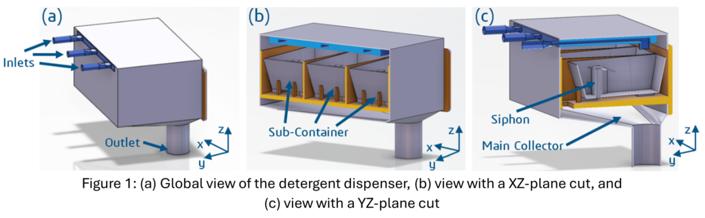
A laundry detergent dispenser is illustrated in Figure 1. It is an abstracted and simplified model of the one found in commercial washing machines. As shown in Figure 1a, the container has three inlets and one major outlet. Figure 1b, where a cross-section cut in the XZ-plane is made, shows that, in the interior of the detergent dispenser, the fluid collects in three sub-compartments before flowing into the collector that is connected to the major outlet. The flow of liquid from one of the inlets, through a sub-container, and then into the bottom collector attached to the main outlet can be seen more clearly in Figure 1c, which shows a cross-section in the YZ-plane.
The fluid flowing into the dispenser is water. To model this situation, a transient Navier-Stokes simulation is set up. By doing so, a multiphase physics domain can be specified in the FMK Fluid Scenario application. By default, the volume of fluid method is selected – it is the only option currently available. The two instantiated phases are air (gas) and water (liquid). The turbulence model chosen is the Realizable k-ε model, which tends to perform better for internal flows. As boundary conditions, each inlet has a water mass flow rate of 0.01 kg/s, and the outlet has a pressure of 0Pa gauge. Since this is a multiphase simulation, where it is crucial to capture the interface between air and water well, a uniformly high convergent volume mesh (CVM) density is used with a maximum mesh size of 1mm. For a container characteristic span of about 200mm, this leads to about 11 million elements. Finally, it is specified that the simulation should have a CFL number of 5, which is sufficiently small for multiphase simulations, and be run for about 4 seconds of physical time.
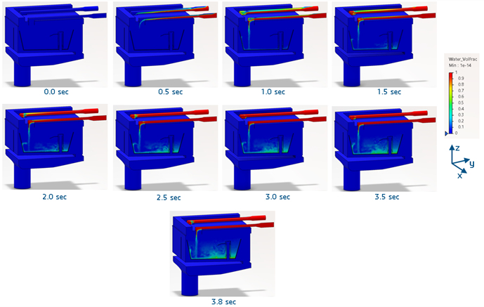
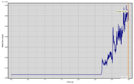
Upon completion of the simulation, a good way to visualize the container tank fill and thereby understand how the laundry detergent dispenser fills over time is to view contour plots of the water volume fraction in the FMK Physics Results Explorer application. This can be seen as a time sequence below in Figure 2. The water enters through its inlet pipes, spreads in and fills up the sub-containers, while rising in the siphons, with the ultimate target being to be discharged into the main collector, where the water is dispelled into the laundry machine drum. To understand when water starts to reach the main outlet, it is useful to view the mass flow rate as a function of time at the outlet plane. This is shown in Figure 3. Evidently, water begins to reach the outlet plane at about 2.65 seconds, and the outlet water mass flow rate continues to rise toward its steady-state value.
How Do You Simulate Airflow Through a Tumble Dryer’s Centrifugal Fan?
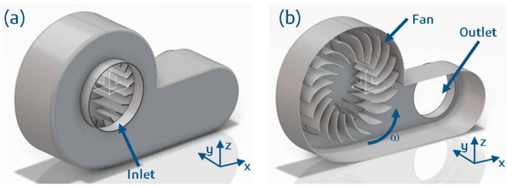
The centrifugal fan of the tumble dryer is illustrated in Figure 4. As with the washing machine detergent dispenser previously discussed, this is an abstracted and simplified model of a radial blower found in commercial tumble dryers. The model contains a casing and a centrifugal blower. As the blower rotates, the fluid enters its core before being expelled radially toward the outlet of the fan casing.
The fluid being pushed through the tumble dryer fan is air. To model this component of a tumble dryer, a two-step process is initiated in the Navier-Stokes-based FMK Fluid Scenario application. First, a steady-state simulation with the fan enclosed by a moving reference frame (MRF) cylinder is performed over 2000 iterations. Then, the velocity and pressure field from the steady-state simulation are used to seed a transient simulation. This transient simulation is run for 0.1 seconds of physical time with a fixed time-step size of 0.001 seconds. Crucially, the MRF has been converted to a sliding mesh, where the fan’s defining mesh actually rotates. In both steps, the Realizable k- model turbulence model is applied, since this is again an internal flow situation. Also, a stagnation inlet, 0Pa gauge pressure outlet and a rotational speed of 2000rpm for the fan are specified. For the mesh, default automatic CVM settings with a maximum element size of about 6mm are used. This leads to a mesh count of about 1.1 million elements for a characteristic domain length of approximately 450mm.
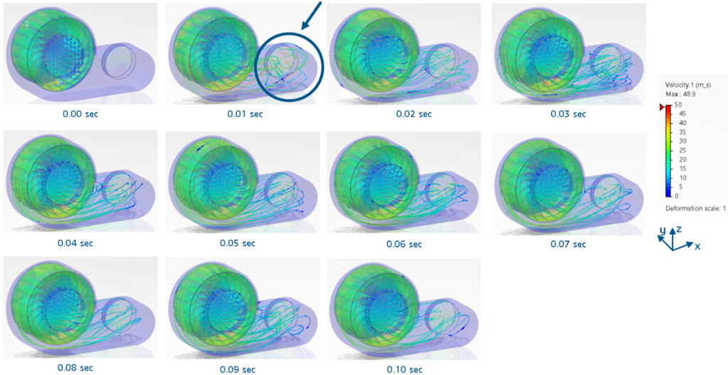
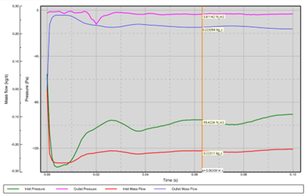
After the two simulations have run, the FMK Physics Results Explorer application should be opened again. To visualize the airflow through the centrifugal fan, streamlines colored by velocity magnitude are instantiated. A sequence of this visualization is shown in Figure 5. There, one can clearly see how the flow enters the center of the centrifugal fan from the inlet of the casing before being expelled radially toward the outlet of the fan casing. As highlighted in Figure 5, the airflow is particularly turbulent at the casing outlet, indicating an area that can be optimized geometrically to improve fan performance. On that note, it is also imperative that the mass flow rate and pressure rise over the radial fan be assessed. This is done using a 2D history plot, as depicted in Figure 6. Mass continuity is maintained since the inlet and outlet mass flow rates are approximately 0.22kg/s. Crucially, a pressure rise of about 92Pa is achieved, indicating that the centrifugal fan successfully pressurizes the airflow before it enters the tumble-drying machine’s plenum.
How Does CFD Help Make Household Appliances More Energy Efficient?
The Home & Lifestyle and High-Tech industries are converging. Complex, highly digitized white-goods machines, such as washing machines and tumble dryers, can no longer be classified solely as part of the Home & Lifestyle sector. Importantly, with the public’s growing awareness of energy consumption and carbon footprint, it is imperative that white-goods manufacturers do everything possible to lower the energy used by their machines. This article illustrates how the virtualization of a washing machine detergent dispenser and a tumble dryer’s centrifugal fan allows tank-fill time and radial fan performance, respectively, to be digitally optimized, thereby addressing energy-efficiency concerns before the machines are produced. Conclusively, it is shown how CFD software native to Dassault Systèmes’ 3DEXPERIENCE Platform can move the world toward a state of sustainable consumption.
What Comes Next: Design Exploration and AI Surrogate Models
There are two main ways that the presented work on household machines can be carried forward. First, the Modeling and Simulation (MODSIM) paradigm of Dassault Systèmes can be applied to both the washing machine detergent dispenser and the tumble dryer’s centrifugal fan, thereby leveraging FMK’s direct connection to the powerful CATIA computer-aided design applications on the 3DEXPERIENCE Platform. More specifically, parameterized models of both components can be submitted as part of a design-of-experiment (DOE) study to better explore the design space associated with tank-fill time and radial fan performance. Second, the topic of artificial intelligence and machine learning must also be considered in the context of future work. It can be envisioned that more rapid DOE studies can be executed with Virtual Twin Physics Behavior (VTB), in which deep learning surrogate models trained on a plethora of FMK simulations enable almost-instantaneous queries of the DOE design space to optimize tank-fill time and fan behavior.
FAQs
The volume of fluid (VOF) method is a CFD technique for simulating two fluids that do not mix, such as air and water. Each mesh cell stores the fraction of its volume occupied by each fluid, which lets the simulation track the free surface between them. VOF is the multiphase method used in the FMK Fluid Scenario application.
The detergent dispenser and the tumble dryer fan both involve internal flows, where fluid moves through enclosed passages. The Realizable k-ε turbulence model tends to perform well for internal flows, so it was used in both studies.
A moving reference frame models a rotating part by solving the flow in a rotating coordinate system while the mesh stays fixed, which allows a fast steady-state solution. A sliding mesh physically rotates the part’s mesh at every time step, which captures time-dependent effects more accurately. In the tumble dryer study, an MRF result was used to initialize a sliding-mesh simulation.
The Courant–Friedrichs–Lewy (CFL) number relates the time step to the mesh size and flow velocity. It indicates how many mesh cells the fluid crosses in one time step. Keeping it small helps a transient simulation stay stable and accurate; a CFL number of 5 was small enough for the detergent dispenser simulation.
The mesh must be fine enough to resolve the interface between the two fluids. In the detergent dispenser study, a uniform maximum element size of 1 mm on a component about 200 mm across produced about 11 million elements. The single-phase fan study used a coarser 6 mm maximum element size and about 1.1 million elements.
Both studies used the Fluid Dynamics Engineer (FMK) role on the Dassault Systèmes 3DEXPERIENCE platform: the FMK Fluid Scenario application to set up and solve the simulations, and the FMK Physics Results Explorer application to visualize and plot the results.
 Dr. Faron Hesse
 graduated with a MEng in mechanical engineering from the Imperial College of London in 2016. During this degree, he worked for one year as an Aerodynamic Performance Engineer at the Red Bull Racing F1 team, winning the championship with Sebastian Vettel. Faron then pursued a sponsored MRes in fluid dynamics, again at the Imperial College of London. Finally, prior to starting to work for Dassault Systèmes in 2019 as an Industry Process Consultant in the T&M Supplier Fluids division, Faron completed a PhD in vehicle aerodynamics at the Imperial College of London.
 Svetlana Jeronimo
Svetlana Bludovskaia Jeronimo is an Industry Process Consultant Manager leading the ECAL SIMULIA Fluids team. She supports customer engagements in CFD: aerodynamics, aeroacoustics, and thermal applications across a wide range of industries. Svetlana holds a Master of Science degree in Computational Engineering from Ruhr University Bochum, with expertise in simulation-driven engineering and fluid dynamics solutions.