
Antenna manufacturers protect their IP by providing only selective information to their customers. In order to analyze installed performance, surrogate antenna models are useful. We will describe how we use Antenna Magus to find surrogate models for placement studies.
IP protected antennas
Every antenna engineer knows the frustration of incomplete datasheets. To protect their intellectual property, many manufacturers don’t include details such as the geometry of the antenna or even the type of radiating structure. This leaves system design engineers unable to easily evaluate how the antenna will perform when installed without actually building and testing a physical prototype.
However, here is the solution that we can offer. From the information given in the datasheet – such as frequency, VSWR, radiation pattern and external views of the radome – we can work backward and generate a model that mimics the performance characteristic of the original antenna.. This surrogate antenna model can then be used in a virtual placement study.
How to find the surrogate antenna model
Our new Best Practices document, “Antenna Magus: from Farfield Cuts to Surrogate Model”, shows how Antenna Magus can take available information from a datasheet to find a surrogate antenna with similar performance characteristics.
This can be done in a few simple stages. First, the user inputs the data as a specification in Antenna Magus. Radiation pattern cuts can be scanned in and traced to automatically calculate KPI’s such as gain and beamwidth. Additional keywords such as “blade”, “monopole” or “wire” can also be used to narrow down the search.
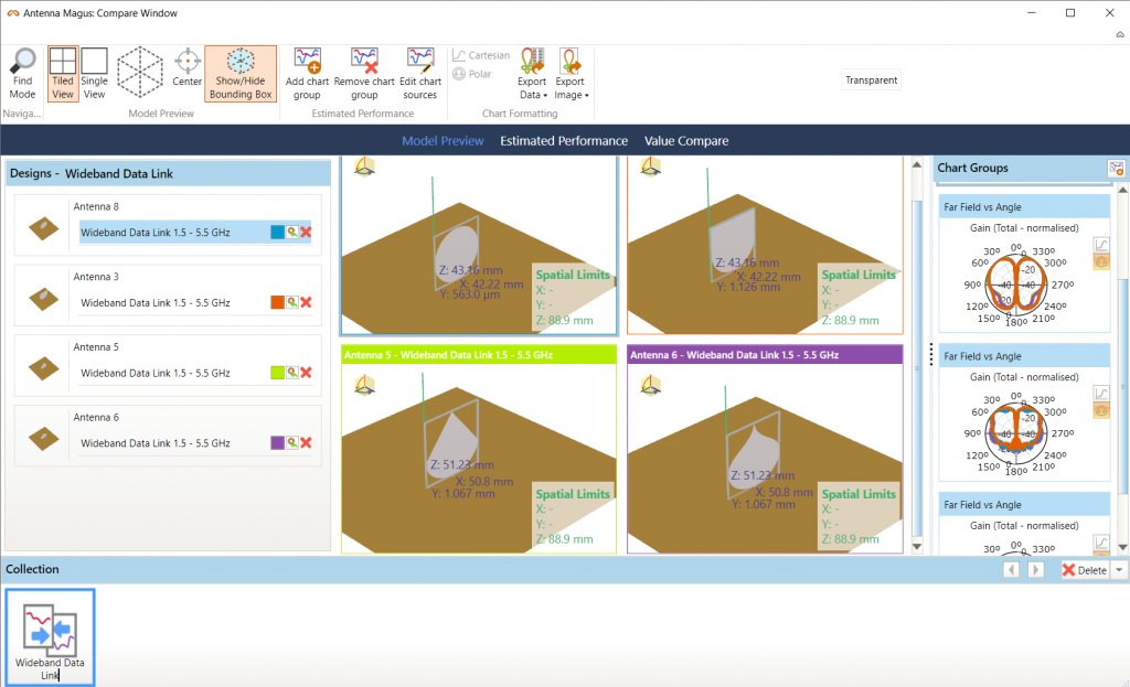
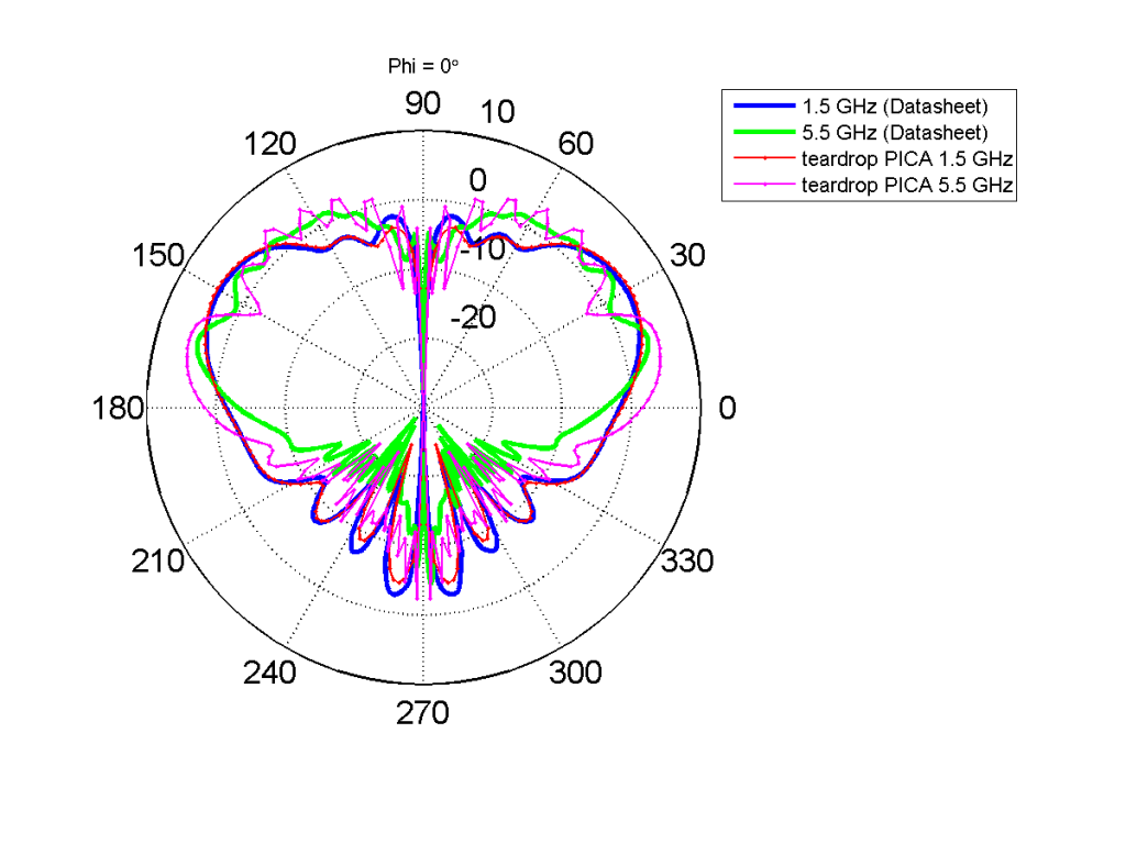
Antenna Magus then searches its extensive library of antenna designs and suggests types of antennas that could have the properties specified by the user (Figure 2). The user can choose the most suitable of these and export the models into SIMULIA CST Studio Suite for detailed 3D modeling and simulation. The automatically generated models can be adjusted as needed (for example, radomes added or ground planes changed) and simulated to verify the antenna still performs according to the datasheet (Figure 3). This verified model can then be used for a detailed full system simulation in SIMULIA CST Studio Suite or using the Antenna Placement App on the 3DEXPERIENCE platform.
For more information about the workflow and a detailed example for a 1.5 – 5.5 GHz Data Link Antenna, see “Antenna Magus: from Farfield Cuts to Surrogate Model”.
SIMULIA offers an advanced simulation product portfolio, including Abaqus, Isight, fe-safe, Tosca, Simpoe-Mold, SIMPACK, CST Studio Suite, XFlow, PowerFLOW and more. The SIMULIA Community is the place to find the latest resources for SIMULIA software and to collaborate with other users. The key that unlocks the door of innovative thinking and knowledge building, the SIMULIA Community provides you with the tools you need to expand your knowledge, whenever and wherever.

Konrad obtained his B.Eng and MSc.Eng degrees in Electrical and Electronic Engineering from the University of Stellenbosch in South Africa in 2004 and 2007 respectively. His Masters Thesis focused on the design of high efficiency RF Doherty power amplifiers. In 2006 he started working at Poynting Antennas (Pty) Ltd as an antenna engineer. In 2008 he joined Magus (Pty) Ltd as an antenna engineer to write antenna design algorithms to be included in the Antenna Magus design software. He remained with Magus during the acquisition by CST AG in 2014 and the subsequent acquisition of CST AG by Dassault Systèmes in 2016. Although still occasionally designing antennas for Antenna Magus his focus has shifted more into the direction of product development for Antenna Magus.