Reference IPE: Brake System Engineering
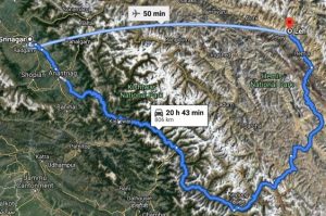
A couple of years ago, I was driving through the mountains from Srinagar to Leh in northern India. On this highway, there are particular patches of mountain passes that are steep and wind with sharp turns.
In a virtual scenario, I was in my DS Bleucar along with a friend. After having driven for a few hours along this highway, we started noticing a burning smell from the brakes of the car. We pulled over and let the brakes cool-down. Then we proceeded at a slower speed towards our destination and started looking for a garage to get the problem fixed. Upon inspection, the mechanic said that typically the brakes develop this problem due to frequent braking at high speeds, causing overheating due to insufficient cooling – and it can also result in temporary reduction in braking power while driving.
Let’s first investigate the phenomenon of brake cooling
During braking action, kinetic energy is converted into heat due to friction. The brake disc absorbs approximately 90% of the total heat and the brake linings absorb the rest of it. This absorbed heat is then dissipated to the brake caliper, rim, and wheel by conduction, and to the surrounding environment by convection and radiation. In this process, if some components fail to dissipate this heat quickly, they tend to overheat. This deteriorates the braking performance and the brakes may even fail if the problem persists. Insufficient flow of cooled air to the brake system can potentially lead to problems like brake fading, cracked rotors, and increased wear between pad and rotor.
How to address this problem?
Well, it is simple. In essence, you need to ensure effective cooling of brake systems for reliable performance. This can be achieved by providing sufficient cooling airflow on heated components such as the brake disc rotor, pads, and caliper to ensure that the heated air escapes from the brake system effectively. Braking heat is removed by using ducts to direct the cooling air into the “eye” of the disc through internal vanes and across the braking faces of the rotor. There also be other ways to improve cooling performance such as making design changes to deflectors to re-direct the cooling air towards the brake system. However, one has to be careful to ensure that any such design changes in the ducts to enhance brake cooling does not adversely lead to an increase in aerodynamic drag and a reduction in fuel efficiency. In essence, one has to optimize the brake duct system design for the desired cooling performance and balance this with aerodynamic drag.
SIMULIA Solution
SIMULIA provides a solution to accurately predict the brake-cooling performance from an early design phase. Using the PowerFLOW and PowerTHERM apps, one can perform detailed thermal simulations taking into account conduction, convection, and radiation heat transfer modes. This helps the user accurately predict the temperature distribution and visualize the heated air flow around critical components of the brake system.
Furthermore, using the Process Apps capabilities from SIMULIA, one can optimize the brake system design for efficient cooling. A streamlined simulation process reduces the turnaround time for model setup, detailed simulation, validation, and design modifications. Quick baseline design changes and CAD-CAE associativity help us evaluate the improvements in brake performance and to track the changes in aerodynamic drag due to design changes driven by brake cooling.
Optimize Brake Cooling Performance
We can set-up a Design-of-Experiments study to understand the changes in the ducts and deflectors and how it could improve the brake cooling performance. We used PowerDELTA in the simulation workflow to create design variants for the ducts and deflectors. These design variants and simulation cases are set-up in PowerCASE and executed using the SIMULIA CLOUD optimization app.

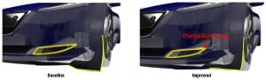
The image below shows the baseline and improved design.
Results
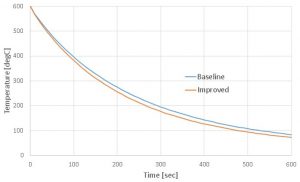
Cooldown time: This is the time taken for the rotor to be cooled down
As you can observe from the plots below, the baseline design was taking 600 seconds for the brake system to cool down from a peak temperature of 600°C to 83°C. With our improved design, we are able to achieve this cooling in 500 seconds.
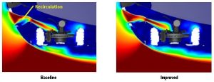
Cooling airflow distribution in the front left brake during braking
We computed the distribution of cooling airflow over the rotating hot brake disc. The flow around the brake parts is highly transient in nature and dependent on the brake cooling airflow ducts, tires and bumper parts. In the baseline design, the re-circulation seems to occur at the duct, which restricts the fresh airflow towards the brake system and this reduces its thermal performance. In our improved design, we were able to eliminate the re-circulation and reduced the cool down time by 50 sec (put the right number here).
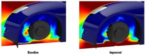
In the baseline design, we have observed that due to the wheel deflectors, the air flow is deflected away from the brake system. In our improved design, shown below, the wheel deflectors are able maintain the airflow towards the brake system, thus improving the thermal performance of the brake system. The wheel deflector is an aerodynamic device and with the improved design, we were able to minimize the penalty on brake cooling.
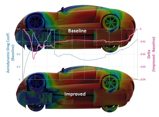
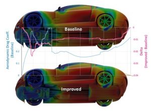
Impact on Aerodynamic Drag
For the baseline design, the aerodynamic drag is higher at the front and it recovers at the rear. The reason is that the larger wheel deflector for the baseline case has a larger high-pressure area due to its size and front wheel wake, though it works better in improving the flow in the rear parts including the base pressure. The improved design has a lower drag at the front but the overall value is about the same.
Conclusion
Designing efficient brake systems is a challenging task trying to achieve multiple design objectives by balancing aerodynamics and brake cooling. Our study shows that by using a coupled simulation approach, and studying different variants of the model, it is possible to achieve balanced aerodynamics and brake cooling targets. The procedure implemented in this work gives the benefit of performing virtual testing at the early stages of the vehicle development, thus eliminating the need for physical prototypes and testing.
See our brake simulation solutions by visiting: https://www.3ds.com/products-services/simulia/solutions/transportation-mobility/brake-system-engineering/
SIMULIA offers an advanced simulation product portfolio, including Abaqus, Isight, fe-safe, Tosca, Simpoe-Mold, SIMPACK, CST Studio Suite, XFlow, PowerFLOW and more. The SIMULIA Learning Community is the place to find the latest resources for SIMULIA software and to collaborate with other users. The key that unlocks the door of innovative thinking and knowledge building, the SIMULIA Learning Community provides you with the tools you need to expand your knowledge, whenever and wherever.

Katie is the Editor of the SIMULIA blog, an expert in engineering and scientific communication, and a strategic digital marketer. Katie has a BA in English and Writing from the University of Rhode Island and a MS in Technical Communication from Northeastern University. She is also a proud SIMULIA advocate, passionate about democratizing simulation for all audiences. Katie is a native Rhode Islander who lives just outside of her favorite city, Providence. She is a true New Englander and loves sharing all the cool things NE has to offer. She enjoys a variety of hobbies including history, astronomy, science/technology, science fiction, true crime, fashion and anything associated with nature and the outdoors. She is also mom to a 6-year old budding engineer and two crazy rescue pups.