

This week I’m continuing the series with a tip on the different point modes in Surpac and just a couple of examples of how they can be used.
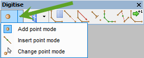
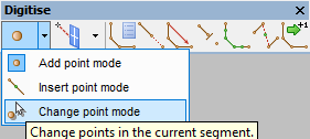
There are 3 point modes in Surpac (Add, Insert and Change) and by default, Surpac generally works in Add point mode. I say generally because there are some functions which only work in Insert point mode or Change point mode.
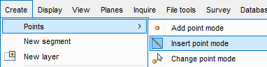
Where do you find the option to change from one point mode to the other? You can find it in a couple of places. The easiest way to switch modes is on the digitizing toolbar.
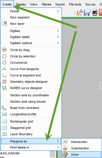
The other option is in the Create menu.

Now we know how to switch between modes, let’s look at a couple of examples of how it affects our workflow.
Union of polygons
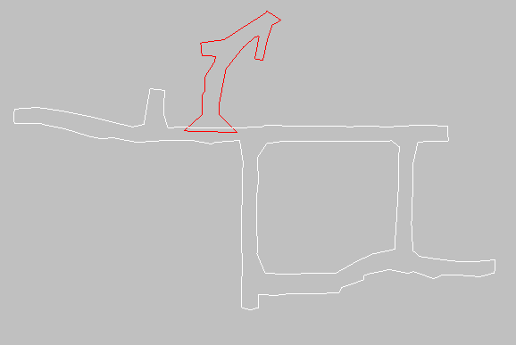
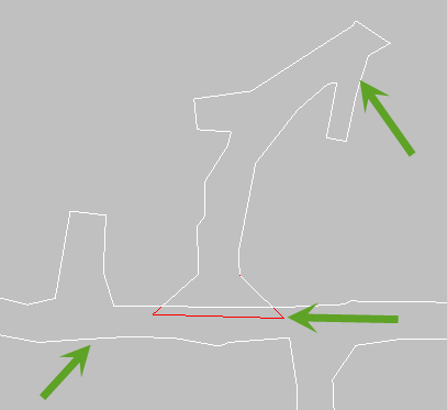
If I have two closed and clockwise polygons, the red polygon represents a new pickup in an underground mine. There are many ways to append this new pickup into the existing drive but let’s union them together. I can switch my mode from Add to Change and then run the function Create Polygons by union.
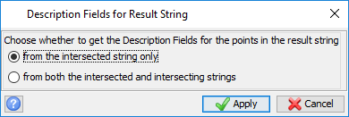
The function will ask if you want to save description fields from one of the strings. There are none in this data so it doesn’t matter which I choose.
You then need to choose the intersecting shape. This is the red polygon in the screen capture above.
Next, click on the intersected shape. This is the white polygon.
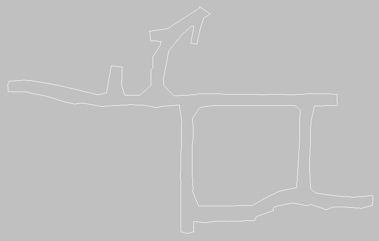
The final result is shown below, a continuous string which is the result of the union in Change point mode.
How would this have looked if we had stayed in Add point mode? We actually end up with:
- The original white polygon;
- The original red polygon; and
- A new white polygon which is the result of the union.
This can cause confusion to the user who now has to delete two segments to see the desired result.
Inserting points when creating underground drive profiles
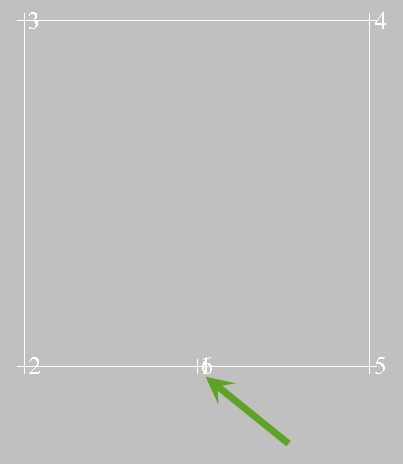
The next point modes example can be demonstrated when creating underground drive profiles. I’ll start with the profile semi complete, in this case it is a 6m by 6m square box that I will fillet the corners of. To be used as an underground drive profile, it is recommended that you create the mid-point of the floor at co-ordinates 0x,0y,0z (Green arrow) Note also that the segment is clockwise.
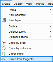
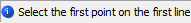
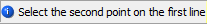
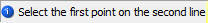
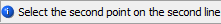
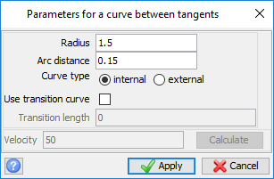
Now switch the point mode to the Insert point mode and run the function Curve from tangents.
Follow the instructions on the status bar by selecting the four points that make up the tangent lines (Start and end of each line).
Fill in the dimensions as below:
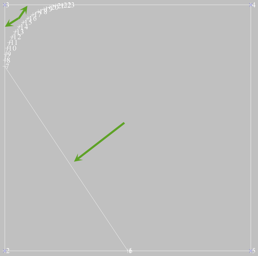
Your result should look like this:
The curve is physically inserted into the segment with the corner point removed and no extra editing is necessary.
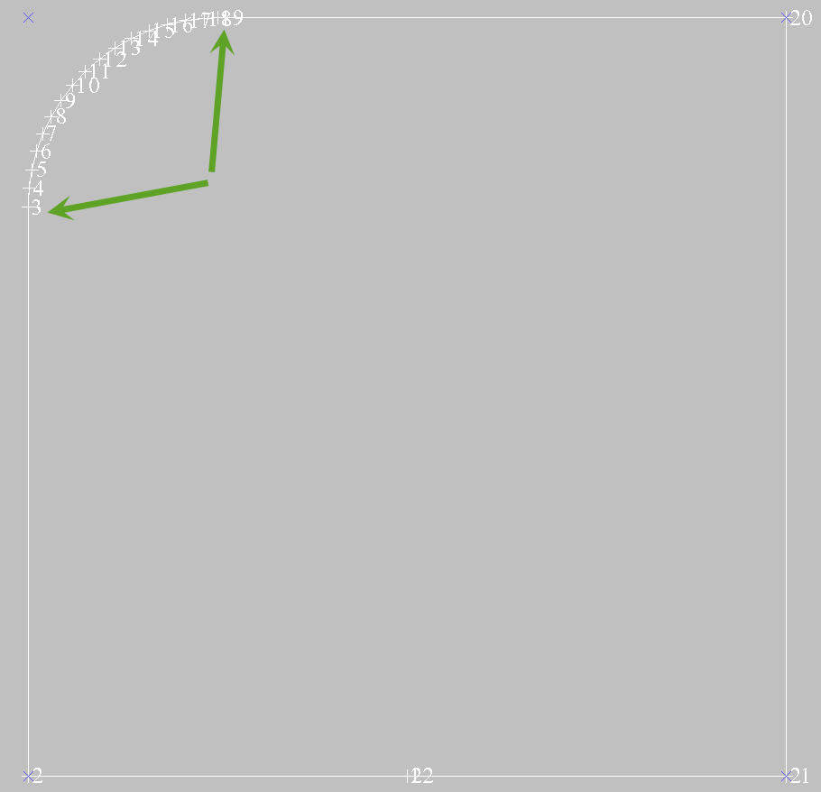
Now, let’s see what it would look like if we had stayed in Add point mode.
The points are just added on to the segment, and in this case it will require extra editing to be useful as a profile string.
If you want to create a solid using the profile string, first save the profile, design a centreline and then use the function Solids >Triangulate >Using Centreline and profile.
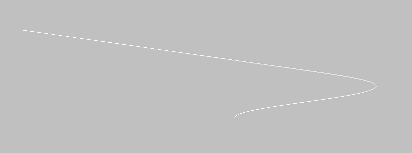
The final result will look like this:
There are many other examples available so I encourage you to have a go at experimenting with the different modes. Remember – when creating any data in Surpac, the goal is to perform as little post-editing as possible, which is usually achievable by switching between modes.
Stay tuned for my next post on using Visual Cutting Planes!
You might also be interested in: