
In July 2019, an American passenger aircraft was unable to land at Dallas airport due to loss of communication with air traffic control (ATC). As a result, the aircraft had to remain in air for 30 minutes thus delaying all successive flights that were scheduled to take off. Airline companies face huge losses due to such delays. Loss of communication with ATC for few minutes is common. In the USA, 5-6 incidents are reported every month. This often occurs due to poor design of the antenna systems.
How do we design reliable antennas?
To answer this question, we need to understand how aircrafts communicate with each other and with Air Traffic Control (ATC). This is possible due to Very High Frequency (VHF) antennas. These antennas are placed on the body of the aircraft and they transmit electromagnetic signals to and from ATC. Transceiver systems at both ends process and convert these signals into sound. However, sometimes antennas fail to capture signals from the ATC causing loss of communication. This could arise due to improper design and placement of antennas or signal interference between multiple antennas (referred to as co-site interference).
In order to eliminate the possibility of such undesirable incidents, we designed and simulated VHF Antennas using SIMULIA’s Electromagnetic tools. We carried out the following steps.
- Selection of Appropriate Antenna.
- Optimization of Antenna Dimensions to achieve Target Center Frequency.
- Optimum Antenna Placement for Minimum Cross-Coupling.
- Elimination of Co-Site Interference between Onboard Antennas.
Selection of Appropriate Antenna
The operating frequency range of VHF antenna systems is 118 to 137 MHz with 127.5 MHz as the center frequency.
There are couple of different design options for VHF antennas –
- Monopole Antenna
- Dipole Antenna
- Loop Antenna
- Notched blade Antenna
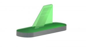
Notched blade antenna was selected for its bandwidth and aerodynamic performance. The blade can be mounted directly on the airframe, which provides grounding to reflect waves, improving the radiation.
A blade VHF antenna is readily available in Antenna Magus, Which is SIMULIA’s antenna design and modelling tool. A radome, which is a dome like structure to protect radar equipment and is made from material transparent to radio waves was designed and placed upon the antenna to make it weatherproof.
Optimization of Antenna Dimensions to Achieve Target Center Frequency
The time-domain electromagnetic simulation that we performed allowed us to determine the actual center frequency of this blade antenna – it was above 130 MHz whereas our target center frequency was 127.5MHz.
Using optimization tools the width and height of the antenna were optimized to achieve the target center frequency.
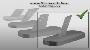
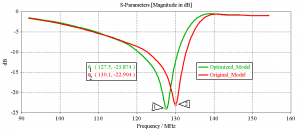
Thus, we now have a VHF antenna that is guaranteed to resonate at 127.5MHz. The next step was to place the antenna on the aircraft.
Optimum Antenna Placement for Minimum Cross-Coupling
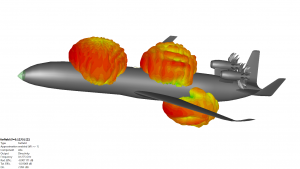
VHF antennas were placed at three different positions on the aircraft – Front, Back and Bottom portion of the Fuselage.
This is done to ensure that there is no loss of communication, no matter how the aircraft is oriented with respect to the ATC.

But since all the antennas are required to operate at the same frequency, sometimes one of the antennas may absorb most of the power radiated from another identical antenna, commonly known as cross-coupling. This degrades the performance of the communication system.
Although unavoidable, cross coupling in well-positioned antennas can be minimized to a great extent! Therefore, an antenna placement study was carried out to find out the best position for each antenna such that the cross-coupling between them was minimized.
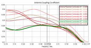
8 different placement combinations were identified. Each combination was rated based on a coupling coefficient. The combination of antenna positions with lowest overall cross coupling was selected. We also found that radiation pattern was uniform and did not have any nulls, which translates to good reception in all directions.
Elimination of Co-Site Interference between Onboard Antennas
Each antenna operates in a designated frequency range to avoid signal interference. But outside its frequency range, an antenna radiates noise which is produced by the transceiver system.
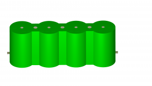
When several antenna systems are located in close proximity with each other, this low amplitude noise is large enough to be detected by nearby antennas. This phenomenon is called Co-site Interference. A given antenna can either be a victim of interference, a source or both.
Moreover, this noise is significantly higher at integral multiples of the frequency of operation of an antenna. For instance, an antenna operating at 1 Gigahertz (GHz) will produce high intensity noise at frequencies 2 GHz, 3 GHz, 4 GHz and so on. This noise is called Harmonic noise.
Since VHF systems operate at a relatively low frequency, harmonic noise from nearby antennas, which generally operate at few GHz cannot harm it. But the VHF system itself produces harmonic noise, which interferes with GPS antenna operating at 1.575 GHz.
The simulations that we performed to study interference also confirmed this.
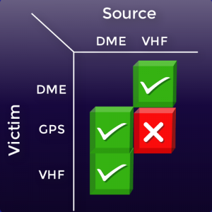
As shown in the above figure, the red box indicates that VHF is the source of interference whereas GPS is the victim.
The next step is to eliminate the interference, while considering the design constraints, which prevent us from altering the design or placement of these antennas further. So how do we eliminate Co-site interference? The answer is to look at Filter Designer 3D, which is SIMULIA’s synthesis tool for band pass and diplexer filter design supporting cross coupling and advanced topologies.
A Filter is a special device that allows antennas to radiate in a specific frequency range, while blocking all unwanted radiation including Harmonic noise.
We were able to quickly synthesize a narrow passband filter for VHF antenna system. The filter response was combined with the VHF antenna simulation data, and interference results were recomputed.
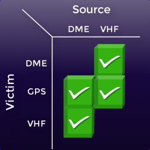
As seen in the above picture for violation matrix, the interference between the VHF and GPS antenna systems was fully eliminated.
Thus, we have ensured a robust antenna design and placement on our aircraft which has helped to achieve the following –
- Our antennas are designed to minimize cross-coupling between the VHF antennas and elimination of co-site interference between VHF and GPS antenna systems.
- This has ensured a reliable and robust communication between aircraft – ATC and aircraft – aircraft.
The aircraft communication systems equipment market is estimated to generate revenue of US$ 15 Billion by 2025, as compared to US$ 7 Billion in 2016.
SIMULIA’s offerings ensure safe and reliable communication systems for aircrafts.
Please see our Aircraft Communication & Detection System Performance Solutions here:
SIMULIA offers an advanced simulation product portfolio, including Abaqus, Isight, fe-safe, Tosca, Simpoe-Mold, SIMPACK, CST Studio Suite, XFlow, PowerFLOW and more. The SIMULIA Learning Community is the place to find the latest resources for SIMULIA software and to collaborate with other users. The key that unlocks the door of innovative thinking and knowledge building, the SIMULIA Learning Community provides you with the tools you need to expand your knowledge, whenever and wherever.

Katie is the Editor of the SIMULIA blog, an expert in engineering and scientific communication, and a strategic digital marketer. Katie has a BA in English and Writing from the University of Rhode Island and a MS in Technical Communication from Northeastern University. She is also a proud SIMULIA advocate, passionate about democratizing simulation for all audiences. Katie is a native Rhode Islander who lives just outside of her favorite city, Providence. She is a true New Englander and loves sharing all the cool things NE has to offer. She enjoys a variety of hobbies including history, astronomy, science/technology, science fiction, true crime, fashion and anything associated with nature and the outdoors. She is also mom to a 6-year old budding engineer and two crazy rescue pups.