
Selective Laser Melting (SLM) is an additive manufacturing process in which parts are built layer-by-layer by a scanning laser beam heating and binding powder. Material is heated locally and rapidly above melting temperature and then allowed to solidify and cool to form a dense geometry. Because this process involves large thermal gradients, residual stresses and distortions are generated in the manufactured part. Predicting these part stresses and distortions prior to a costly manufacturing process can ensure build success and that the part will perform under the required service loading.
To date, numerous validations of simulating the additive manufacturing software process have been performed on calibration type specimens and microstructure predictions. These coupon level or building block level validations have proven the accuracy of the SIMULIA capabilities for simulating the additive manufacturing process, and the next step is to understand the accuracy in predicted distortions of complex industrial parts.
Morf3D and SIMULIA teamed up to investigate distortion predictions of a Ti6Al4V part, manufactured by SLM. The results were presented at the recent AIAA SciTech Forum, January 6-10 in Orlando, Florida. In this study, a complex topology optimized gimbal mount component from an Unmanned Aerial System, as shown in Figure 1, was considered for physical printing and finite element analysis of the print process.
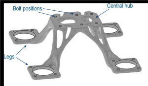
The component was built at Morf3D Aerospace using an EOS M290 machine having a 400W Yb-fibre laser with a spot size diameter of 100 𝜇𝑚. The EOS M290 system has a standard build volume of 250 x 250 x 325 mm. Once the build was complete and cooled down to room temperature, the part was removed from the build plate using wire EDM and the supports were removed with hand tools. CMM measurements were then taken, for more than 0.3M points around the outer profile of the part.
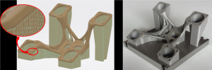
The additive manufacturing framework on the 3DEXPERIENCE platform was used to perform SLM process simulations using finite element analysis. Before performing the simulation, build preparation operations (positioning and support structures) were completed digitally to emulate the physical print, and a laser scan path for the build was generated using the physical print process parameters (laser power, scan speed, recoater timing, layer thickness, etc). A sequentially coupled thermal mechanical analysis was then performed to predict temperatures, distortions, and residual stresses. The laser scan path provided a temporally and spatially accurate heat loading for the thermal analysis, balanced by cooling on the evolving free surfaces of the part during the build. For the structural analysis, mechanical properties of Ti6Al4V were obtained from the manufacturer’s datasheet and Johnson-Cook hardening plasticity was used. In both the thermal and structural analyses, additional steps were added after the build analysis to include cooling the part to room temperature, removing the part from the build plate, and finally removing the support structures from the part.
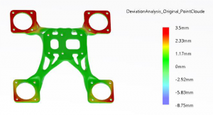
In order to understand the complex part distortions from the build process, first a deviation analysis was done between the original CAD geometry and a mesh recreated from the CMM measurement points. These results represent the experimental deviations obtained from the physical build and are shown in Figure 3. Clearly two of the four legs exhibit significant distortions, shown in the red contour regions.
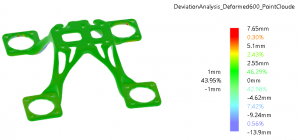
Next, to compare the simulation results with the experimental results, a CAD representation of the simulated distorted part was generated using Digital Morphing capabilities in the 3DEXPERIENCE platform. Finally, a deviation analysis between the predicted distorted part and the mesh recreated from measurement points showed good correlation in the results, as shown in Figure 4.
To read the full paper, please click on the link, here.
SIMULIA offers an advanced simulation product portfolio, including Abaqus, Isight, fe-safe, Tosca, Simpoe-Mold, SIMPACK, CST Studio Suite, XFlow, PowerFLOW and more. The SIMULIA Learning Community is the place to find the latest resources for SIMULIA software and to collaborate with other users. The key that unlocks the door of innovative thinking and knowledge building, the SIMULIA Learning Community provides you with the tools you need to expand your knowledge, whenever and wherever.

Katie is the Editor of the SIMULIA blog, an expert in engineering and scientific communication, and a strategic digital marketer. Katie has a BA in English and Writing from the University of Rhode Island and a MS in Technical Communication from Northeastern University. She is also a proud SIMULIA advocate, passionate about democratizing simulation for all audiences. Katie is a native Rhode Islander who lives just outside of her favorite city, Providence. She is a true New Englander and loves sharing all the cool things NE has to offer. She enjoys a variety of hobbies including history, astronomy, science/technology, science fiction, true crime, fashion and anything associated with nature and the outdoors. She is also mom to a 6-year old budding engineer and two crazy rescue pups.