
As the Internet of Things (IoT) establishes itself, more and more connected devices are finding their way into the modern home. The “connections” are of course wireless and antennas are the key enabling technology that provides that wireless connectivity. This article will use the example of a smart projector (Figure 1) to talk about the simulation techniques and tools that allow new antenna concepts for connected IoT-enabled devices to be developed and tested quickly at a very early design stage, leading to a device with improved connectivity and a reduced overall design time.
Antenna design is not an activity performed in isolation. The antenna engineer has to keep pace with changing constraints during the multiple stages of a dynamic product design cycle, being able to respond quickly to the question of how many of what kind of antenna should be placed where in the device in order to have acceptable communication links. Current communication standards are of immediate interest, but the antenna engineer must also be equipped to explore concepts for future standards such as 5G. The tools and approaches described here allow the engineer to do just that.
ANTENNA SELECTION
The objective of the antennas is to provide connectivity for the device for particular communication standards – in this case WLAN 2.4 and Bluetooth – so it has to operate efficiently in the relevant frequency ranges. A key constraint in compact devices such as our projector is the amount of space available for the antennas. One option is to source an off-the-shelf antenna module from a supplier and assign space for it on the printed circuit board (PCB). However, better performance and more design flexibility can be obtained by using multiple custom-designed antennas integrated at suitable locations. The combination of the antenna design tool Antenna Magus and CST STUDIO SUITE makes custom design a realistic option.
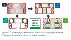
As device design constraints change over several design cycles – see for example the range of projector frame shapes and available antenna locations in Figure 2 – the constraint based design ability of Antenna Magus is invaluable. Given a frequency range and a size constraint, Antenna Magus produces a shortlist of suitable antenna types that can be further filtered visually by the antenna engineer.
Changes in the available space can be introduced to the constraints in Antenna Magus. The shortlist is automatically updated and new parametric antenna designs filter to the top of the list. Having a range of options is important since it allows the engineer to make trade-offs in terms of manufacturing, feeding, and robustness, but also in order to allow complementary antennas chosen to provide better overall reception coverage.
ANTENNA PLACEMENT WORKFLOW
The initial antenna design is not done with a particular placement in mind. The antenna performance is highly dependent on its position in the device, so this effect has to be evaluated and the antenna design adjusted, or matching circuitry added, so that it still performs according to specification.
In order to investigate multiple possible configurations quickly, it is essential that set-up and simulation of the model is robust and fast, and that relevant key performance indicators (KPIs) are produced directly without additional user input. An efficient set-up of the simulation model is facilitated by the System Assembly Modelling (SAM) framework, which allows multiple components to be easily assembled, each contributing their geometry, materials and mesh settings to the full device model, as shown in Figure 3.
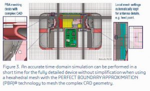
A time domain simulation based on a hexahedral mesh with the PERFECT BOUNDARY APPROXIMATION (PBA)® technology to accurately resolve complex CAD without simplification or healing gives all relevant results – S-parameters near-fields (Figure 4) and farfields (Figure 5) – quickly.
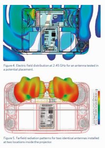
When multiple antennas are installed, it is not only their individual farfield behavior but their combined performance that is of interest. Automatic post-processing allows quantities like the Total Scan Pattern (TSP) coverage to be evaluated, as shown in Figure 6.
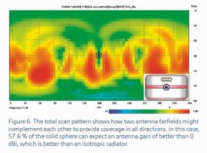
The TSP gives the maximum gain of either antenna in each direction, and can be used as a figure of merit to compare multiple antenna placement scenarios with each other. The type of marked difference between configurations shown in Figure 7 could not be predicted without using simulation.

CONCLUSION AND OUTLOOK
In order to design a functioning communication link for a complex consumer electronic device, the antenna engineer needs tools that allow them quickly and accurately to evaluate multiple integrated antenna design scenarios. The tools and methods described in this article show a viable approach. As communication bandwidths increase and higher frequency standards such as 5G establish themselves, new antenna technologies may become viable. The antenna will likely have to be designed as an integral part of the device housing itself. Multidisciplinary simulation across different physical domains will be required and the combination and interaction of tools accessible through the 3DEXPERIENCE platform will present the ideal environment for sustainable innovation in the future.
For more information: www.cst.com/beamy

Marc Rütschlin is a SIMULIA R&D Roles Portfolio Engineering Director, working on the technical formulation, positioning and marketing of microwave and high frequency related electromagnetic simulation solutions in the High-Tech and other industries. Prior to his current role, Marc worked for CST as a Principal Engineer, global Market Development Manager (MW&RF) and Industry Development Manager (High Tech). He joined CST in 2007 after completing his PhD in Electronic Engineering at the University of Stellenbosch, South Africa, and post-doctoral studies at NIST in Boulder, Colorado, and at the University of Karlsruhe in Germany, working on electromagnetic wave propagation in buildings and small antenna design respectively.