
Today’s tip talks about how to use offset display for multi-lift projects or sub-level caving projects.
When working with a multi-lift project, sometimes there is an overlap between the two lifts. This makes it difficult to graphically view the two lifts together on a plan view section. An offset can be placed on the layout to shift it so that the lifts are no longer displayed with an overlap.
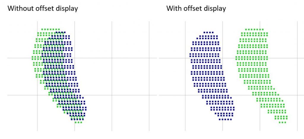
The images below show the plan view of a multi-lift layout without and with the offset display.
Assigning Drawpoints to Each Lift
The Sector, Production Block, or Group field in the draw point workspace can be used to identify each lift. In this example the Sector field will be used to map drawpoints from Lift1 and Lift2. This step only needs to be done if the drawpoints have not already been assigned to each lift
There are many methods to assign drawpoints to sectors. The example below will show how to do it through Excel. The Sector field can be set by exporting the draw points to Excel.
Go to PCBC > Drawpoints > Export Drawpoint Data to Excel.
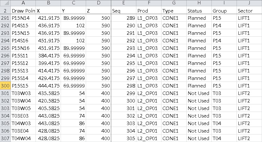
Below is a view of the drawpoint data once it is exported to Excel. Drawpoints on a different lift can be identified by their elevation and the Sector field can be set according to the elevation. The drawpoint name could also be used to identify each lift depending on the naming convention that is used.
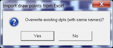
Once the sector field has been updated, you can import the drawpoints back into PCBC. Go to PCBC > Drawpoints > Import Drawpoints from Excel.
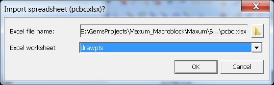
Select the Excel file and sheet with the drawpoint data.
Define offset values
The offset for each lift is defined through an offset bucket. The bucket assigns an offset value to each drawpoint.
The offset value for each lift is set up in Excel. In Excel, offset values are defined for each sector. In this example, LIFT2 will be offset 350m to the East of its current location.
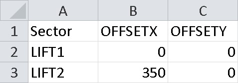
The excel sheet is defined below:
Column A – Name of Sector, Production Block, or Group. Row 1 is the name of the grouping field
Column B – Offset value in the X direction. Row 1 is the name of the bucket
Column C – Offset value in the Y direction. Row 1 is the name of the bucket.
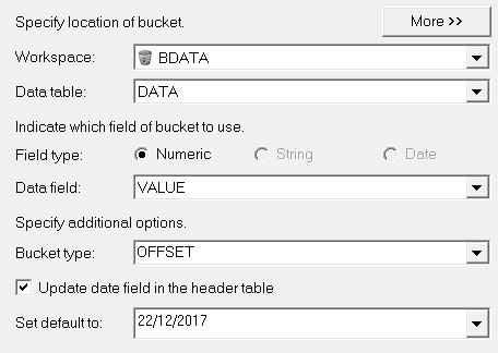
Import these values as a bucket. Go to PCBC > Buckets > Transfer Bucket Data between Workspace and Excel.
Select the Excel file and worksheet with the offset data. Select the option “Get data from Excel”.
Select the workspace to import the bucket data into.
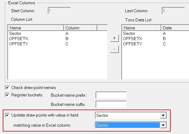
Move Sector, OFFSETX, and OFFSETY over to the right hand side. Down at the bottom check on the option “Update draw points with value in field”.
Select the Sector field and the Sector column in excel. This option will link the drawpoints based on the sector field. In this example the name of the bucket will be OFFSETX and OFFSETY.
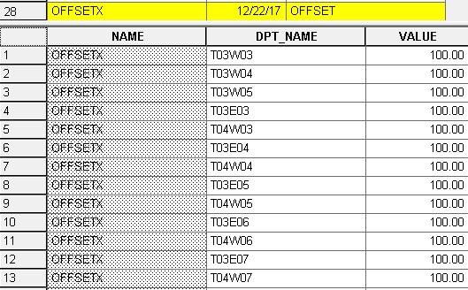
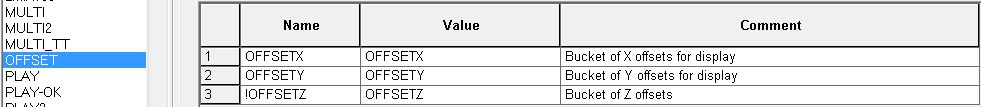
Below is a view of the bucket data in the Data Editor.
Displaying the offset
To display the drawpoint layout with an offset, an OFFSET advanced profile needs to be created. The value in the advanced profile will be the name of the bucket.
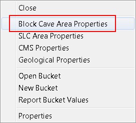
Once the offset advanced profile is created, it needs to be applied to the caving area. Right click on the caving area and select the Block Cave Area Properties.
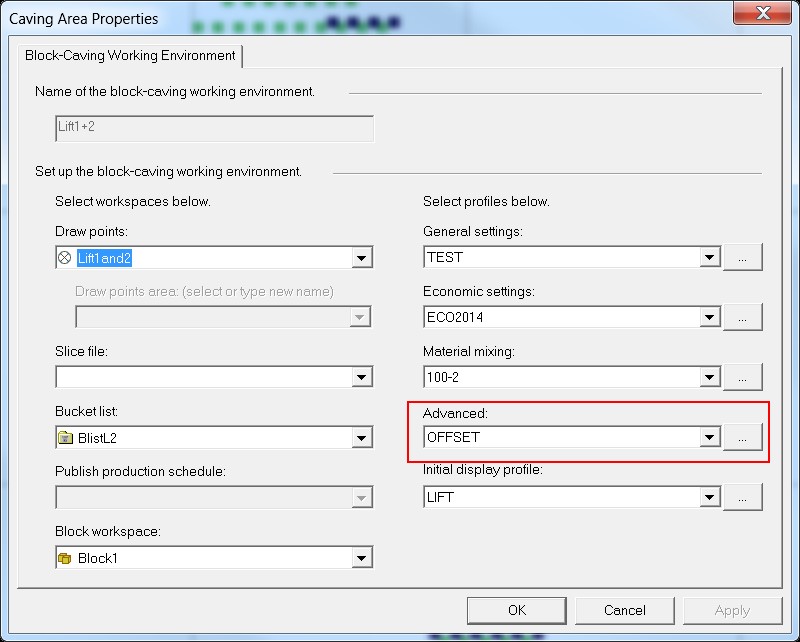
Update the Advanced profile to the OFFSET advanced profile by selecting it in the drop down list.
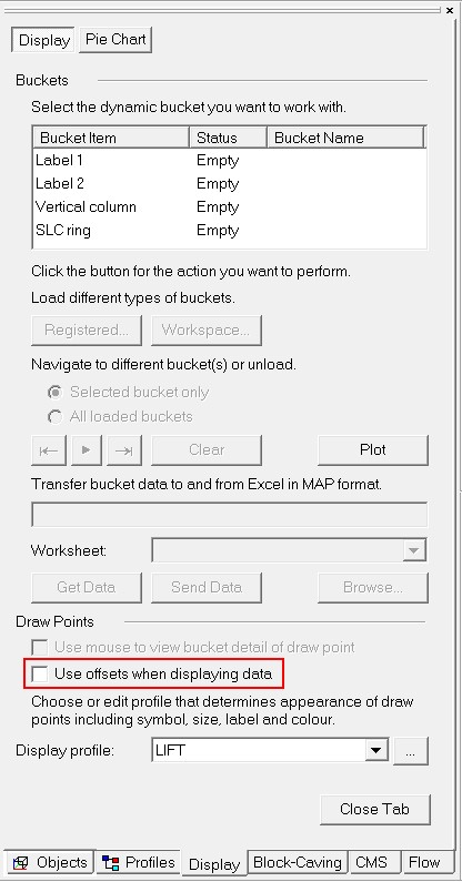
The offset display can be easily toggled on and off. Go to the Display tab in the Project View Window and check on the box “Use offsets when displaying data”.
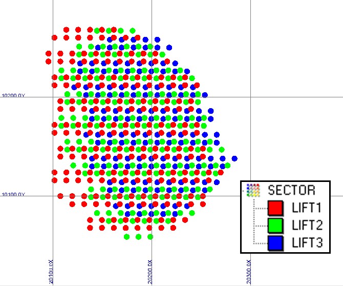
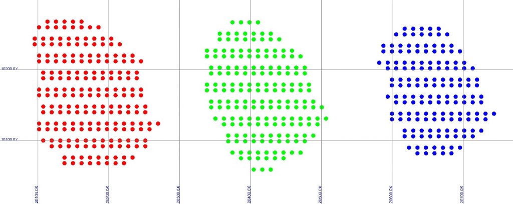
The images below show the display of a three lift project without and with the offset display.
Without offset display
With offset display
For more PCBC tips, check out:

Truong joined the GEOVIA brand at Dassault Systèmes in 2010 and has been focused on solution implementations at client sites and software training. Truong joined the GEOVIA Caving Business Unit in 2012, where he has worked on many different block caving projects, from order of magnitude to feasibility studies, as well as being involved in sub-level caving projects.